•
PCI slot connectors:
–
For 2U PCI riser card assembly:
–
PCI slot 1:
Insert a full-height, full-length PCI Express adapter into this slot.
–
PCI slot 2:
Insert a full-height, half-length PCI Express adapter into this slot.
–
PCI slot 3:
Insert a low-profile PCI Express adapter into this slot.
–
PCI slot 4:
Insert a low-profile PCI Express adapter into this slot.
–
PCI slot 5:
Insert a low-profile PCI Express adapter into this slot.
–
For 1U PCI riser card assembly:
–
PCI slot 1:
Insert a full-height, half-length PCI Express adapter into this slot.
–
PCI slot 2:
Insert a low-profile PCI Express adapter into this slot.
–
PCI slot 3:
Insert a low-profile PCI Express adapter into this slot.
•
USB connectors:
Connect a USB device, such as USB mouse or keyboard to either of these connectors.
•
Power supplies:
Each power supply has a dc power LED and an ac power LED. When the dc power LED
is lit, it indicates that the power supply is supplying adequate dc power to the system. During normal
operation, both the ac and dc power LEDs are lit. For any other combination of LEDs, see “Power-supply
LEDs” on page 24.
•
NMI button:
Press this button to force a nonmaskable interrupt to the microprocessor. It allows you to
blue screen the server and take a memory dump (use this button only when directed by the service
support). You might have to use a pen or the end of a straightened paper clip to press the button.
•
Serial connector:
Connect a 9-pin serial device to this connector. The serial port is shared with the
integrated management module II (IMM2). The IMM2 can take control of the shared serial port to perform
text console redirection and to redirect serial traffic.
•
Video connector:
Connect a monitor to this connector. The video connectors on the front and rear of
the server can be used simultaneously.
Note:
The maximum video resolution is 1600 x 1200 at 75 Hz.
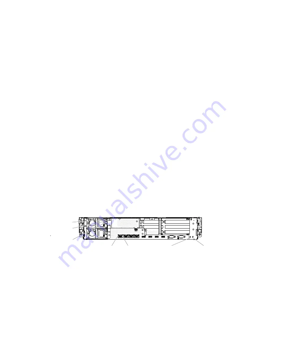
The following illustration shows the LEDs on the rear of the server.
0000000
0000000
0000000
0000000000
0000000000
0000000000
00000
Ethernet
activity LED
Ethernet link
LED
AC LED (green)
DC LED (green)
Power supply
error LED (yellow)
-
System locator
LED
System error
LED
•
Ethernet activity LEDs:
When these LEDs are lit, they indicate that the server is transmitting to or
receiving signals from the Ethernet LAN that is connected to the Ethernet port.
•
Ethernet link LEDs:
When these LEDs are lit, they indicate that there is an active link connection on the
10BASE-T, 100BASE-TX, or 1000BASE-TX interface for the Ethernet port.
•
AC power LED:
Each hot-swap power supply has an AC power LED and a DC power LED. When the AC
power LED is lit, it indicates that sufficient power is coming into the power supply through the power
cord. During typical operation, both the AC and DC power LEDs are lit. For any other combination
of LEDs, see “Power-supply LEDs” on page 24.
•
DC power LED:
Each hot-swap power supply has a DC power LED and an AC power LED. When the
DC power LED is lit, it indicates that the power supply is supplying adequate DC power to the system.
During typical operation, both the AC and DC power LEDs are lit. For any other combination of LEDs,
see “Power-supply LEDs” on page 24.
.
The Lenovo System x3630 M4 Type 7158 server
23
Summary of Contents for System x3630 M4
Page 1: ...Lenovo System x3630 M4 Installation and Service Guide Machine Type 7158 ...
Page 6: ...iv Lenovo System x3630 M4 Installation and Service Guide ...
Page 14: ...xii Lenovo System x3630 M4 Installation and Service Guide ...
Page 108: ...94 Lenovo System x3630 M4 Installation and Service Guide ...
Page 134: ...120 Lenovo System x3630 M4 Installation and Service Guide ...
Page 186: ...172 Lenovo System x3630 M4 Installation and Service Guide ...
Page 844: ...830 Lenovo System x3630 M4 Installation and Service Guide ...
Page 868: ...854 Lenovo System x3630 M4 Installation and Service Guide ...
Page 1026: ...1012 Lenovo System x3630 M4 Installation and Service Guide ...
Page 1030: ...1016 Lenovo System x3630 M4 Installation and Service Guide ...
Page 1038: ...Taiwan BSMI RoHS declaration 1024 Lenovo System x3630 M4 Installation and Service Guide ...
Page 1040: ...1026 Lenovo System x3630 M4 Installation and Service Guide ...
Page 1049: ......
Page 1050: ......


