Notes:
1. Before you replace the system board, make sure that you backup any features on demand (FoD) keys
that were enabled. Remember to re-enable the features on demand (FoD) keys after installing the new
system board. For more information on Features on Demand (FoD), including instructions for automating
the activation and installation of the activation key by using ToolsCenter or Systems Director, see the
Features on Demand User's Guide
at https://fod.lenovo.com/lkms under the Help section.
2. When you reassemble the components in the server, be sure to route all cables carefully so that they
are not exposed to excessive pressure and that they do not get pinched when you reinstall the system
board (see “Internal cable routing” on page 173 and “System-board internal connectors” on page 30 for
more information). In addition, make sure the cables are inserted into the relevant cable clips.
3. When you replace the system board, you must either update the server with the latest firmware or
restore the pre-existing firmware that the customer provides on a diskette or CD image. Make sure
that you have the latest firmware or a copy of the pre-existing firmware before you proceed. See
“Updating the firmware ” on page 95, “Updating the Universal Unique Identifier (UUID)” on page 114,
and “Updating the DMI/SMBIOS data” on page 116 for more information.
Important:
Some cluster solutions require specific code levels or coordinated code updates. If the device is
part of a cluster solution, verify that the latest level of code is supported for the cluster solution before you
update the code
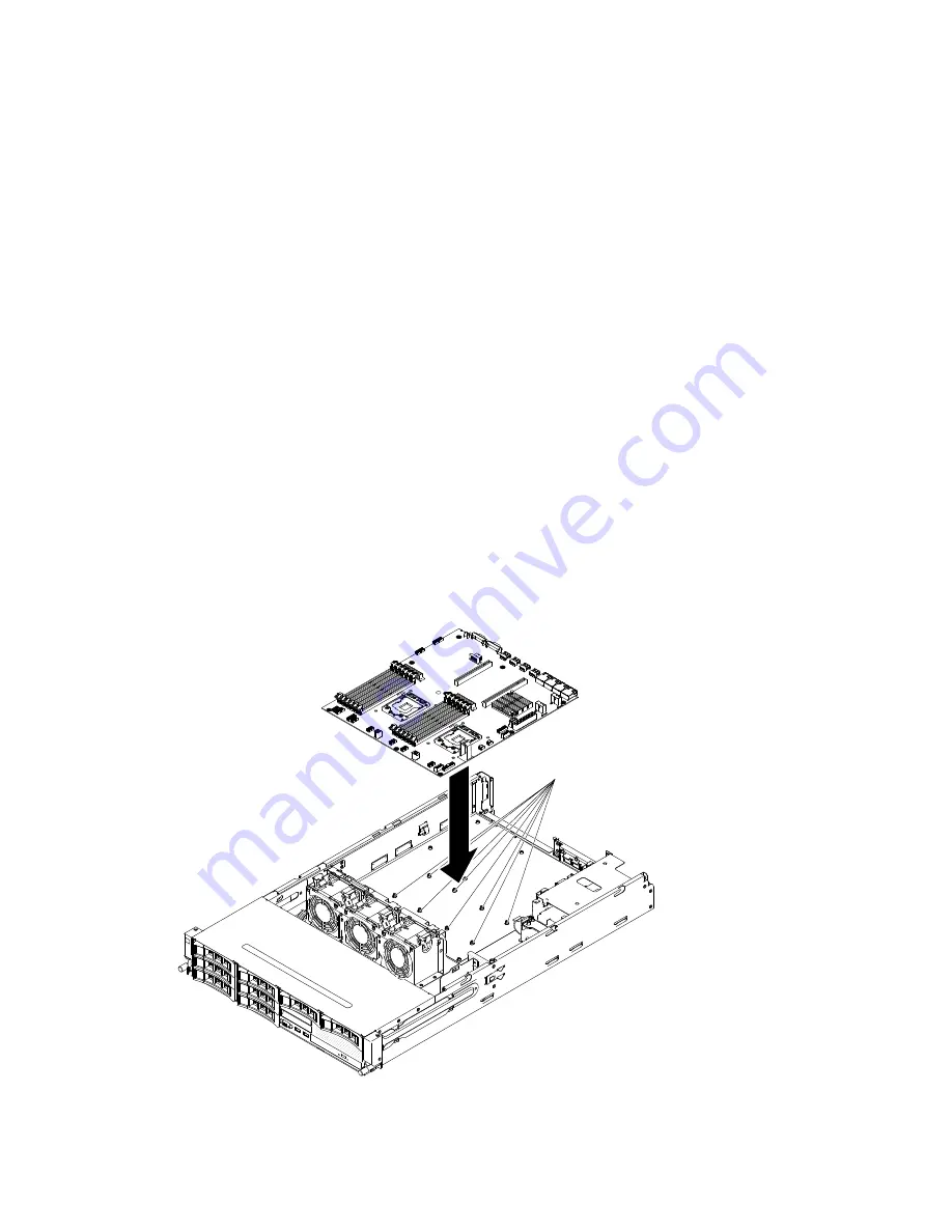
To install the system board, complete the following steps:
Step 1.
Read the safety information that begins in “Safety” on page v and “Installation guidelines” on
page 36.
Step 2.
Lower the system board into the chassis. Pay attention to the positions of the standoffs as they
will be used later.
000
000
00000
00000
00000
00000
00000
Standoffs
Step 3.
Gently push the system board by the side nearest to the fan cage to insert the external input/output
connectors into their respective holes in the chassis.
Removing and replacing components
317
Summary of Contents for System x3630 M4
Page 1: ...Lenovo System x3630 M4 Installation and Service Guide Machine Type 7158 ...
Page 6: ...iv Lenovo System x3630 M4 Installation and Service Guide ...
Page 14: ...xii Lenovo System x3630 M4 Installation and Service Guide ...
Page 108: ...94 Lenovo System x3630 M4 Installation and Service Guide ...
Page 134: ...120 Lenovo System x3630 M4 Installation and Service Guide ...
Page 186: ...172 Lenovo System x3630 M4 Installation and Service Guide ...
Page 844: ...830 Lenovo System x3630 M4 Installation and Service Guide ...
Page 868: ...854 Lenovo System x3630 M4 Installation and Service Guide ...
Page 1026: ...1012 Lenovo System x3630 M4 Installation and Service Guide ...
Page 1030: ...1016 Lenovo System x3630 M4 Installation and Service Guide ...
Page 1038: ...Taiwan BSMI RoHS declaration 1024 Lenovo System x3630 M4 Installation and Service Guide ...
Page 1040: ...1026 Lenovo System x3630 M4 Installation and Service Guide ...
Page 1049: ......
Page 1050: ......


