2H0/2HZ-1
1-5-56
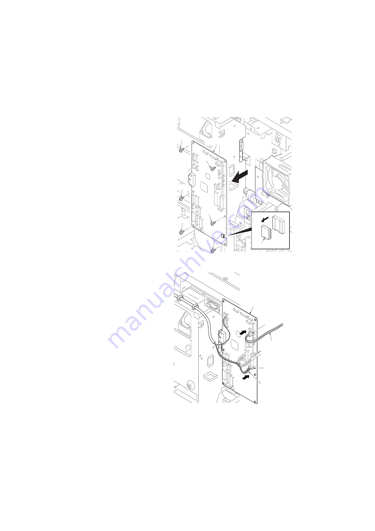
6. Remove all connectors of engine PWB.
7. Remove six screws and remove the engine
PWB.
8. Replace the engine PWB and install the
PWB.
Figure 1-5-102
9. Refit all the removed parts.
When replacing the connectors back in
place, be sure not to mistake YC14 and
YC20 for each other.
YC14: Wire of the eject motor
YC20: Wire of the key counter
Figure 1-5-103
Engine PWB
Screw
Screw
Screw
Screw
Screw
Screw
EEPROM
U3
Engine PWB
4-pin connector
(YC20)
4-pin connector
(YC14)
Wire of
the key counter
(connect to YC20)
Wire of
the eject motor
(connect to YC14)
Summary of Contents for KM-2560
Page 1: ...SERVICE MANUAL Published in April 2008 842H0112 2H0SM062 Rev 2 KM 2560 KM 3060 ...
Page 4: ...This page is intentionally left blank ...
Page 10: ...This page is intentionally left blank ...
Page 14: ...2H0 2HZ This page is intentionally left blank ...
Page 20: ...2H0 2HZ 1 1 6 This page is intentionally left blank ...
Page 36: ...2H0 2HZ 2 1 2 16 This page is intentionally left blank ...
Page 262: ...2H0 2HZ 2 1 20 This page is intentionally left blank ...
Page 323: ...INSTALLATION GUIDE FOR PAPER FEEDER ...
Page 324: ...CAUTION 注 意 2007 6 303K656810 注 意 PRECAUCION VORSICHT ATTENZIONE ATTENTION ...
Page 347: ...INSTALLATION GUIDE FOR BUILT IN FINISHER ...
Page 359: ...INSTALLATION GUIDE FOR JOB SEPARATOR ...
Page 369: ...INSTALLATION GUIDE FOR FAX System M ...
Page 385: ...INSTALLATION GUIDE FOR Data Security Kit C ...
Page 388: ...INSTALLATION GUIDE FOR UG 30 ...
Page 391: ......
Page 392: ......


