DOCUMENT NUMBER: 139-01GB-02
PAGE: 1/2
EQUIPMENT: GC
SERVICE INFO NUMBER: 139
REVISION DATE: MARCH , 2008
REVISED BY: JÖNSSOH
SERVICE INFORMATION
CURRENT RELAY SETTINGS
This service information contains information about the settings
and replacement of the current relays, used for low current
alarm of the heating.
The manufacturer has changed the design in June 2004 and
due to this the settings of the relay have been affected.
DIB01 current relay
Note!
From June 2004 the SJ155 is replaced by the new DIB01 relay.
Supply connection
For the DIB01 relay the supply connections are 11 and 10, for
24 VAC. See illustration 1.2.
Replacement
On some equipment the 1 - 5 A relay is installed with an exter-
nal shunt resistor. When replacing this relay, make sure to
remove the shunt resistor and use the 10 A version of the new
relay.
Setting
Set the front potentiometers as follows:
HYS = 10%
LEVEL = Current
DELAY = 1-3 sec.
To access the DIP switches open the grey plastic cover. Set the
DIP switches to the
!
-marked value, according to illustration 1.3.
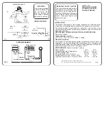
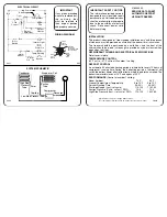
1.1 The new DIB01 current relay.
N (-)
8
9
5
7
10
1
11 4
3
2
48/230 VAC 24/115 VAC
µ
L
1.2 Supply connection DIB01.
10A Models
0.1 - 5 A Models
Relay working mode
ON: Normally De-energized*
OFF: Normally Energized
Power ON delay
ON: 6 s ± 0.5 s
OFF: 1 s ± 0.5 s*
Contact input
ON: Latch function enable
OFF: Inhibit function enable
Monitoring function
ON: Over current
OFF: Under current*
Relay working mode
ON: Normally De-energized*
OFF: Normally Energized
Measuring range
SW1
ON
ON
OFF
SW2
OFF
ON
ON
Power ON delay
ON: 6 s ± 0.5 s
OFF: 1 s ± 0.5 s*
Contact input
ON: Latch function enable
OFF: Inhibit function enable
Monitoring function
ON: Over current
OFF: Under current*
1A 2A 5A
1 2 3 4 5 6
ON
ON
1 2 3 4
1.3 DIP switch setting.
Summary of Contents for FoodTech Frigoscandia GYRoCOMPACT M7
Page 1: ...0 INSTALLATION MANUAL Frigoscandia GYRoCOMPACT M7 Spiral Freezer...
Page 2: ...N...
Page 4: ...INSTALLATION 2 2 INTRODUCTION 02 INSTALLATION MANUAL...
Page 6: ...2 2 0000 07 01 01 00 INSTALLATION MANUAL INSTALLATION...
Page 8: ...2 2 0000 07 01 02 00 INSTALLATION MANUAL INSTALLATION...
Page 16: ...10 0000 00 01GB 11 24 SAFETY...
Page 20: ...SAFETY 4 1000 07 01GB 02 03...
Page 34: ...6 INSTALLATION PREPARATIONS 1000 07 01GB 05 03...
Page 42: ...8 DELIVERY INFORMATION 0000 03 01GB 11 09...
Page 44: ...2 INSTALLATION 1000 07 01GB 07 01 INSTALLATION MANUAL...
Page 48: ...2 INSTALLATION 1000 07 01GB 09 03 INSTALLATION MANUAL...
Page 54: ...2 INSTALLATION 1000 07 01GB 12 00 INSTALLATION MANUAL...
Page 58: ...4 INSTALLATION 1000 07 01GB 13 01 INSTALLATION MANUAL...
Page 62: ...2 INSTALLATION 1000 07 01GB 15 00 INSTALLATION MANUAL...
Page 70: ...2 INSTALLATION INSTALLATION MANUAL 1000 07 01GB 18 01...
Page 72: ...2 INSTALLATION 1000 07 01GB 20 00 INSTALLATION MANUAL...
Page 78: ...6 INSTALLATION 1000 07 01GB 22 03 INSTALLATION MANUAL...
Page 90: ...4 INSTALLATION 1000 07 01GB 29 00 INSTALLATION MANUAL...
Page 110: ...6 INSTALLATION 1000 07 01GB 25 01 INSTALLATION MANUAL...
Page 128: ...18 INSTALLATION 1000 07 01GB 26 06...
Page 144: ...2 INSTALLATION 1000 07 01GB 19 00 INSTALLATION MANUAL...
Page 152: ...2 INSTALLATION 1000 07 01GB 36 00 INSTALLATION MANUAL...
Page 194: ...10 221 01GB 03 SERVICE INFO...
Page 200: ...10 171 01GB 02 SERVICE INFO...
Page 222: ...172 347 01GB 00 SERVICE INFO...
Page 230: ...10 039 01GB 03 SERVICE INFORMATION...
Page 256: ...172 CORRECTIVEMAINTENANCE 1000 06 01GB 10 11...
Page 269: ...Automatic Pump Station PZC M1 PZE M2 CIP M3 Directions for use 3 19 EN...
Page 277: ...9 ALTO Danmark A S...


