


Goodrive350 series high-performance multifunction VFD
Function parameter list
-261-
Function
code
Name
Description
Default
value
Modify
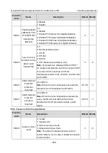
P26.23
Relay RO5
switch-on delay
0.000s
○
P26.24
Relay RO5
switch-off delay
0.000s
○
P26.25
Relay RO6
switch-on delay
0.000s
○
P26.26
Relay RO6
switch-off delay
0.000s
○
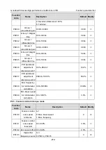
P26.27
Relay RO7
switch-on delay
0.000s
○
P26.28
Relay RO7
switch-off delay
0.000s
○
P26.29
Relay RO8
switch-on delay
0.000s
○
P26.30
Relay RO8
switch-off delay
0.000s
○
P26.31
Relay RO9
switch-on delay
0.000s
○
P26.32
Relay RO9
switch-off delay
0.000s
○
P26.33
Relay RO10
switch-on delay
0.000s
○
P26.34
Relay RO10
switch-off delay
0.000s
○
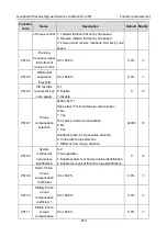
P26.35
AO2 output
selection
The same with P06.14
0
○
P26.36
AO3 output
selection
0
○
P26.38
Lower limit of
AO2 output
Above function codes define the relation between
output value and analog output. When the output
value exceeds the set max./min. output range, the
upper/low limit of output will be adopted during
calculation.
When analog output is current output, 1mA
corresponds to 0.5V voltage. In different
applications, 100% of output value corresponds to
different analog outputs.
0.0%
○
P26.39
Corresponding
AO2 output of
lower limit
0.00V
○
P26.40
Upper limit of
AO2 output
100.0%
○
P26.41
Corresponding
AO2 output of
upper limit
10.00V
○


