Intel® Server System M50FCP1UR System Integration and Service Guide
81
6.9.2
OCP* Adapter with Internal Lock Replacement
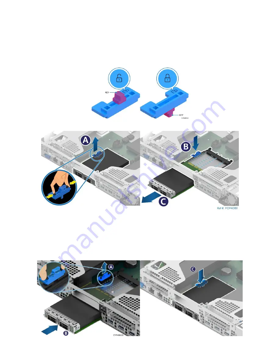
All L6 and L9 integrated systems come with an internal lock on the internal OCP mounting rail. This lock is a
piece of blue plastic. The OCP rail in the system has a dedicated space to accommodate the lock. The lock
can be mounted on the rail in two different orientations. When the keying features of the lock are facing up,
it is in an unlocked orientation. When the keying features are facing down, it is in a locked orientation. A lock
symbol is included in each side of the plastic lock to indicate its orientation. The following figure shows the
features of the lock.
Figure 110. Internal Lock with Unlock and Lock Orientation
Figure 111. OCP* Adapter with Internal Lock Removal
1.
Remove the system top cover (see
Section 6.1.1
2.
(If present) Remove the riser card assembly from above the OCP adapter area (see
Section 6.6
3.
Squeeze the two hooks of the internal lock and pull it from the chassis (see Letter A).
4.
Turn the lock over and reinstall it back into the chassis (see Letter B).
5.
Push the OCP adapter out of the bay from inside the chassis (see Letter C).
Figure 112. OCP* Adapter with Internal Lock Installation
Summary of Contents for M50FCP1UR
Page 2: ...2 This page intentionally left blank...
Page 118: ...Intel Server System M50FCP1UR System Integration and Service Guide 118 1 2 3 4 5 6 1 2 3...
Page 119: ...Intel Server System M50FCP1UR System Integration and Service Guide 119 1 2 3 4 5...
Page 120: ...Intel Server System M50FCP1UR System Integration and Service Guide 120 7 8 9 10 11 12 4 5 6...
Page 121: ...Intel Server System M50FCP1UR System Integration and Service Guide 121 6 7 8 9 10...
Page 130: ...Intel Server System M50FCP1UR System Integration and Service Guide 130 1 2 3 4 5 ESD 6 1 2 3...
Page 131: ...Intel Server System M50FCP1UR System Integration and Service Guide 131 1 2 3 4 5...


