Intel® Server System M50FCP1UR System Integration and Service Guide
85
6.12
Backplane Replacement
Depending on the system configuration, the Intel® Server System M50FCP1UR includes either a 4 x 2.5”
backplane or 12 x 2.5” backplane. This section provides the procedures necessary to replace both types.
6.12.1
4 X 2.5” Backplane Replacement
Required Tools and Supplies
•
Intel backplane kit
•
Anti-static wrist strap and conductive anti-static wrist strap and conductive workbench pad
(recommended)
•
Phillips* head screwdriver #1
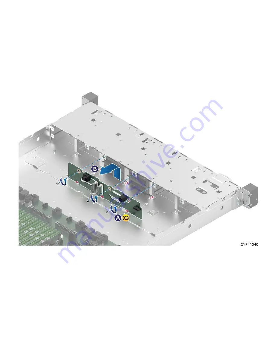
Figure 118. 4 x 2.5” Backplane Removal
1.
Power off the system and disconnect the system power cords.
2.
Remove the system top cover (see
Section 6.1.1
3.
Remove all drives and drive blanks from the front drive bays. NOTE: If drives are configured to a RAID
partition, label the drives to identify the drive bay location they were removed from.
4.
Disconnect all cables from the backplane. NOTE: If drives are configured to a RAID partition, label
each drive I/O cable to identify the backplane cable connection they were disconnected from.
5.
Remove the three screws securing the backplane to drive bay (see Letter A).
6.
Lift the backplane up from the chassis base and pull it out from the system (see Letter B).
Summary of Contents for M50FCP1UR
Page 2: ...2 This page intentionally left blank...
Page 118: ...Intel Server System M50FCP1UR System Integration and Service Guide 118 1 2 3 4 5 6 1 2 3...
Page 119: ...Intel Server System M50FCP1UR System Integration and Service Guide 119 1 2 3 4 5...
Page 120: ...Intel Server System M50FCP1UR System Integration and Service Guide 120 7 8 9 10 11 12 4 5 6...
Page 121: ...Intel Server System M50FCP1UR System Integration and Service Guide 121 6 7 8 9 10...
Page 130: ...Intel Server System M50FCP1UR System Integration and Service Guide 130 1 2 3 4 5 ESD 6 1 2 3...
Page 131: ...Intel Server System M50FCP1UR System Integration and Service Guide 131 1 2 3 4 5...


