Intel® Server System M50FCP1UR System Integration and Service Guide
39
3.4.1
Drive Blank Removal
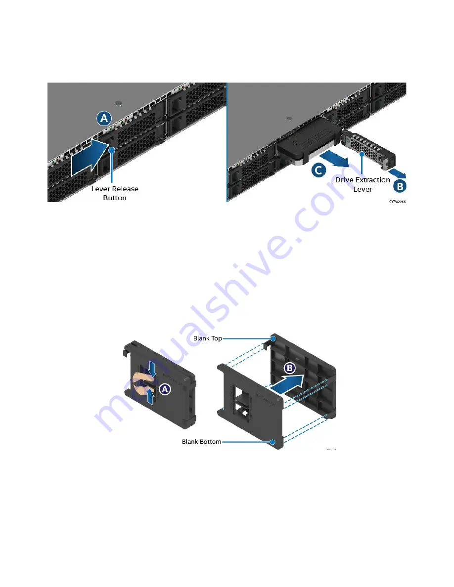
Each drive carrier includes a 2.5” drive blank. Drive blanks should only be removed when replacing it with an
SSD.
Figure 38. Drive Blank Removal
1.
Press the button on the drive extraction lever to release it. See Letter A.
2.
Using the lever, pull the drive rail out from the drive bay as far as it allows (see Letter B).
3.
Pull the drive blank from the drive bay (see Letter C).
3.4.2
7 mm 2.5” SSD Drive Support
All drive bays can support a 2.5” SSD that has a height of 7mm. To support these drives, a section of the
drive blank is used to mount to the SSD, making it compatible for installation into the drive bay.
Figure 39. Separating Top and Bottom Parts of Drive Blank
1.
Remove the drive blank from the system (see
Section 3.4.1
2.
One side of the drive blank has a latch used to secure both halves of the drive blank together. To
separate the halves, squeeze the latch tabs together (see Letter A), and pull the two halves apart (see
Letter B).
3.
The blank half without the latch is used as the SSD mounting bracket
Summary of Contents for M50FCP1UR
Page 2: ...2 This page intentionally left blank...
Page 118: ...Intel Server System M50FCP1UR System Integration and Service Guide 118 1 2 3 4 5 6 1 2 3...
Page 119: ...Intel Server System M50FCP1UR System Integration and Service Guide 119 1 2 3 4 5...
Page 120: ...Intel Server System M50FCP1UR System Integration and Service Guide 120 7 8 9 10 11 12 4 5 6...
Page 121: ...Intel Server System M50FCP1UR System Integration and Service Guide 121 6 7 8 9 10...
Page 130: ...Intel Server System M50FCP1UR System Integration and Service Guide 130 1 2 3 4 5 ESD 6 1 2 3...
Page 131: ...Intel Server System M50FCP1UR System Integration and Service Guide 131 1 2 3 4 5...


