


XC161 Derivatives
Peripheral Units (Vol. 2 of 2)
The Analog/Digital Converter
User’s Manual
16-2
V2.2, 2004-01
ADC_X1, V2.1
The external analog reference voltages
V
AREF
and
V
AGND
are fixed. The separate supply
for the ADC reduces the interference with other digital signals. The reference voltages
must be stable during the reset calibration phase and during an entire conversion, to
achieve a maximum of accuracy.
The sample time as well as the conversion time is programmable, so the ADC can be
adjusted to the internal resistances of the analog sources and/or the analog reference
voltage supply (you may also want to refer to application note AP2428).
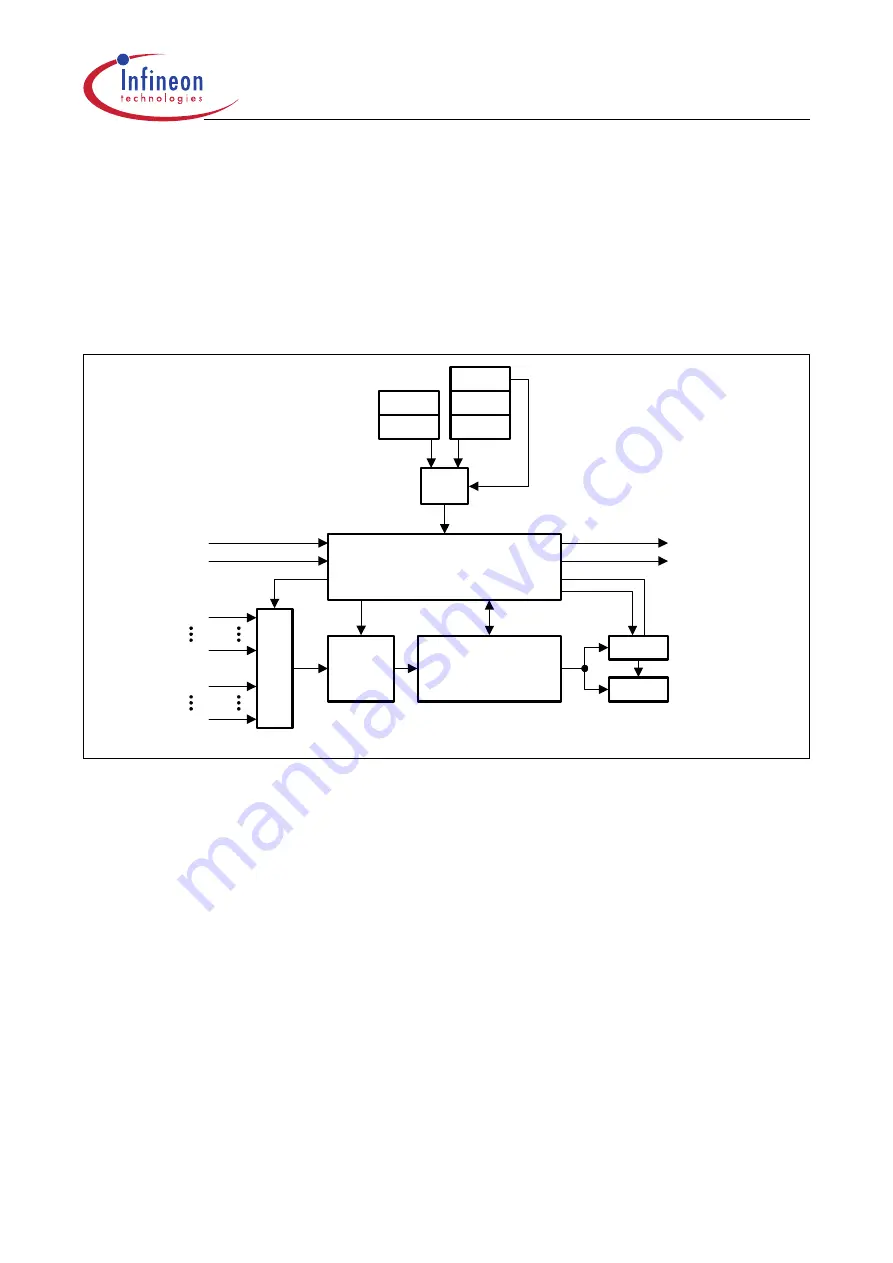
Figure 16-2
Analog/Digital Converter Block Diagram
The ADC is implemented as a capacitive network using successive approximation
conversion. A conversion consists of 3 phases.
•
During the sample phase, the capacitive network is connected to the selected analog
input and is charged or discharged to the voltage of the analog signal.
•
During the actual conversion phase, the network is disconnected from the analog
input and is repeatedly charged or discharged via
V
AREF
during the steps of
successive approximation.
•
After the (optional) post-calibration phase (to adjust the network to changing
conditions such as temperature) the result is written to the result register and an
interrupt request is generated.
There are two sets of control, data, and status registers, one set for compatibility mode
and one set for enhanced mode. Only one of these register sets may be active at a given
time. As most of the bits and bitfields of the registers of the two sets control the same
functionality or control the functionality in a very similar way, the following description is
organized according to the functionality, not according to the two register sets.
MCB05416
Conversion Control
ADC_CIRQ
Sample
&
Hold
8/10-bit
Capacitive Network
Conversion
ADC_EIRQ
MU
X
CON1
CTR2IN
CON
CTR2
CTR0
DAT
DAT2
MUX
AN0
AN7
AN12
AN15
Requests
Injection


