


XC161 Derivatives
Peripheral Units (Vol. 2 of 2)
The General Purpose Timer Units
User’s Manual
14-12
V2.2, 2004-01
GPT_X1, V2.0
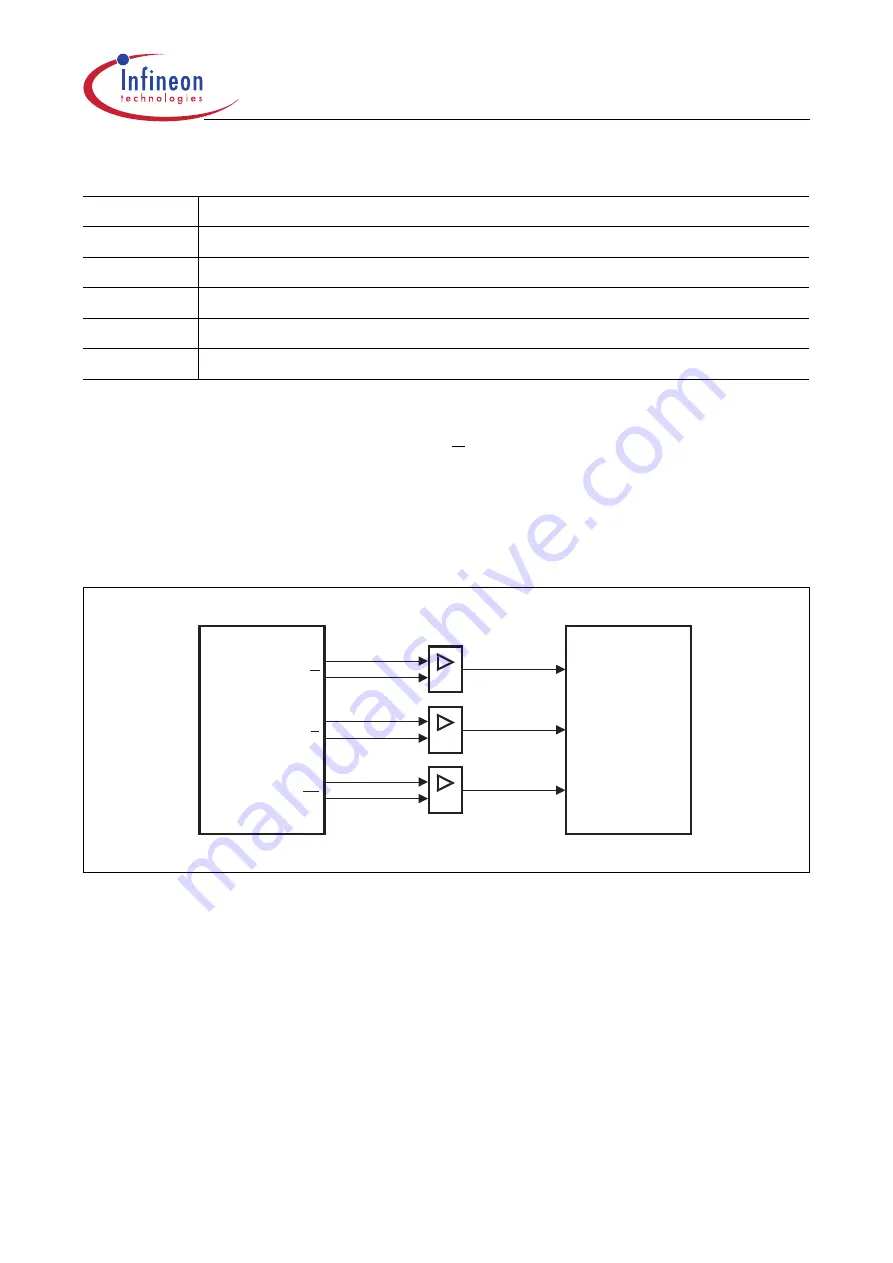
The incremental encoder can be connected directly to the XC161 without external
interface logic. In a standard system, however, comparators will be employed to convert
the encoder’s differential outputs (such as A, A) to digital signals (such as A). This greatly
increases noise immunity.
Note: The third encoder output T0, which indicates the mechanical zero position, may
be connected to an external interrupt input and trigger a reset of timer T3 (for
example via PEC transfer from ZEROS).
Figure 14-8
Connection of the Encoder to the XC161
For incremental interface operation, the following conditions must be met:
•
Bitfield T3M must be 110
B
or 111
B
.
•
Both pins T3IN and T3EUD must be configured as input, i.e. the respective direction
control bits must be 0.
•
Bit T3UDE must be 1 to enable automatic external direction control.
The maximum count frequency allowed in incremental interface mode depends on the
selected prescaler value. To ensure that a transition of any input signal is recognized
correctly, its level must be held high or low for a minimum number of module clock cycles
before it changes. This information can be found in
.
Table 14-3
Core Timer T3 (Incremental Interface Mode) Input Edge Selection
T3I
Triggering Edge for Counter Increment/Decrement
0 0 0
None. Counter T3 stops.
0 0 1
Any transition (rising or falling edge) on T3IN.
0 1 0
Any transition (rising or falling edge) on T3EUD.
0 1 1
Any transition (rising or falling edge) on any T3 input (T3IN or T3EUD).
1 X X
Reserved. Do not use this combination.
MCS04372
Encoder
Controller
A
B
T0
T3Input
T3Input
Interrupt
A
B
B
T0
T0
A
Signal
Conditioning


