Computer Room Emergency Power Off (EPO)
When the integrated battery feature (IBF) is installed and the room EPO is tripped, the batteries will
engage and the computer will continue to run. It is possible to attach the computer room EPO system to
the machine EPO. When this is done, tripping the room EPO will disconnect all power from the line cords
and the internal battery backup unit. In this event all volatile data will be lost.
To incorporate the IBF into the room Emergency Power Off systems (EPO), a cable must be made to
connect to the back of the system EPO panel. The following diagrams illustrate how this connection is
made.
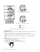
The preceding figure illustrates the back of the machine UEPO panel with the room EPO cable plugging
into the machine. Notice the switch actuator. After it is moved to make the cable connection possible, the
room EPO cable must be installed for the machine to power on.
In the following figure, an AMP connector 770019-1 is needed to connect to the system EPO panel. For
room EPO cables using wire sizes #20 AWG to #24 AWG, use AMP pins (part number 770010-4). This
connection should not exceed 5 Ohms, which is approximately 200 ft.(61 m) of #24 AWG.
1
2
AMP Connector
Part Number - 770019-1
Contact Number
2 Pole Normally Closed Pushbutton
3
4
Machine-Holdup Times
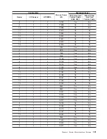
The following tables illustrate typical machine-holdup times (time vs. load) for fresh and aged batteries.
v
All times are listed in minutes
Chapter 2. Physical Characteristics of Systems
103
Summary of Contents for 7012 397
Page 1: ...RS 6000 and Eserver pSeries Site and Hardware Planning Information SA38 0508 20...
Page 2: ......
Page 3: ...RS 6000 and Eserver pSeries Site and Hardware Planning Information SA38 0508 20...
Page 11: ...Appendix Notices 385 Index 387 Contents ix...
Page 12: ...x Site and Hardware Planning Information...
Page 16: ...xiv Site and Hardware Planning Information...
Page 18: ...xvi Site and Hardware Planning Information...
Page 26: ...8 Site and Hardware Planning Information...
Page 238: ...220 Site and Hardware Planning Information...
Page 246: ...228 Site and Hardware Planning Information...
Page 284: ...266 Site and Hardware Planning Information...
Page 296: ...278 Site and Hardware Planning Information...
Page 366: ...348 Site and Hardware Planning Information...
Page 372: ...Async Adapter Cable Planning Chart 354 Site and Hardware Planning Information...
Page 377: ...Standard I O Cable Planning Chart Chapter 12 Cable Planning 359...
Page 380: ...Cable Planning Chart Other Adapters 362 Site and Hardware Planning Information...
Page 384: ...366 Site and Hardware Planning Information...
Page 402: ...384 Site and Hardware Planning Information...
Page 404: ...386 Site and Hardware Planning Information...
Page 413: ......
Page 414: ...Printed in USA SA38 0508 20...
Page 415: ...Spine information RS 6000 and Eserver pSeries Site and Hardware Planning Information...


