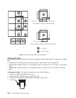
The minimum service clearance for systems with acoustical doors is shown in the following illustration.
Single-Frame System
with Acoustical Doors
d=1295 mm (51.0 in.)
e=914 mm (36.0 in.)
f=1511 mm (59.5 in.)
G=1808 mm (71.2 in.)
f (alternate)=1765 mm (69.5 in.)
e
d
f
26 in.
(660 mm)
f
A
e
d
f (alternate)
26 in.
(660 mm)
f (alternate)
A
Single-Frame System
with Acoustical Doors
(alternative right-side
service clearance)
8.8 in.
(222 mm)
8.8 in.
(222 mm)
8.8 in.
(222 mm)
Refer to the illustration in “Guide for Raised-Floor Preparation” on page 104 for service clearances shown
in a raised-floor installation.
Cooling Requirements
The
Eserver
pSeries 655 requires air for cooling. As shown in
″
Proposed Floor Layout for Multiple
Systems
″
Eserver
pSeries 655 systems must face front-to-front. The use of a
raised floor is recommended to provide air through perforated floor panels placed in rows between the
fronts of systems (the cold aisles shown in the figure on page 116).
The following table provides system cooling requirements based on system configuration. The letter
designations in the table correspond to the letter designations in the graph shown in “Cooling
Requirements Graph” on page 119.
118
Site and Hardware Planning Information
Summary of Contents for 7012 397
Page 1: ...RS 6000 and Eserver pSeries Site and Hardware Planning Information SA38 0508 20...
Page 2: ......
Page 3: ...RS 6000 and Eserver pSeries Site and Hardware Planning Information SA38 0508 20...
Page 11: ...Appendix Notices 385 Index 387 Contents ix...
Page 12: ...x Site and Hardware Planning Information...
Page 16: ...xiv Site and Hardware Planning Information...
Page 18: ...xvi Site and Hardware Planning Information...
Page 26: ...8 Site and Hardware Planning Information...
Page 238: ...220 Site and Hardware Planning Information...
Page 246: ...228 Site and Hardware Planning Information...
Page 284: ...266 Site and Hardware Planning Information...
Page 296: ...278 Site and Hardware Planning Information...
Page 366: ...348 Site and Hardware Planning Information...
Page 372: ...Async Adapter Cable Planning Chart 354 Site and Hardware Planning Information...
Page 377: ...Standard I O Cable Planning Chart Chapter 12 Cable Planning 359...
Page 380: ...Cable Planning Chart Other Adapters 362 Site and Hardware Planning Information...
Page 384: ...366 Site and Hardware Planning Information...
Page 402: ...384 Site and Hardware Planning Information...
Page 404: ...386 Site and Hardware Planning Information...
Page 413: ......
Page 414: ...Printed in USA SA38 0508 20...
Page 415: ...Spine information RS 6000 and Eserver pSeries Site and Hardware Planning Information...


