CAUTION:
If the reading is other than infinity, do not proceed! You must make the necessary wiring
corrections to satisfy the above criteria before continuing. Do not turn on the branch circuit
CB until all the above steps are satisfactorily completed.
__ 7.
Remove tag S229-0237, which reads “Do Not Operate.”
__ 8.
Turn on the branch circuit CB. Measure for appropriate voltages between phases. If no voltage is
present on the receptacle case or grounded pin, the receptacle is safe to touch.
__ 9.
With an appropriate meter, verify that the voltage at the outlet is correct.
__ 10. Verify that the grounding impedance is correct by using the ECOS 1020, 1023, B7106, or an
appropriately approved ground impedance tester.
__ 11. Turn off the branch circuit CB.
__ 12. Attach tag S229-0237, which reads “Do Not Operate.”
__ 13. You are now ready to install and connect the power cables to the
Eserver
pSeries 655. Refer to
Chapter 1 of the
Eserver
pSeries 655 Installation Guide for this procedure.
Dual Power Installation
Some
Eserver
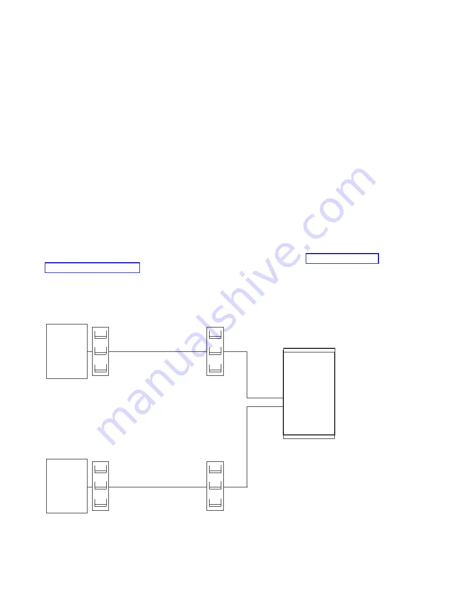
pSeries 655 configurations are designed with a fully redundant power system. These
systems have two line cords attached to two power input ports which, in turn, power a fully redundant
power distribution system within the system. To take full advantage of the redundancy/reliability that is built
into the computer system, the system must be powered from two distribution panels. Larger
Eserver
pSeries 655 configurations require power from two line cords, and they do not have redundant line cords.
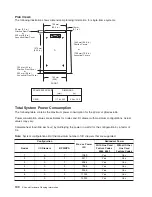
The possible power installation configurations are described as follows. See “Total System Power
Consumption” on page 100 for additional information about power.
Dual Power Installation - Redundant Distribution Panel and Switch:
This configuration requires that
the system receives power from two separate power distribution panels. Each distribution panel receives
power from a separate piece of building switch gear. This level of redundancy is not available in most
facilities.
System
Switch Gear
Distribution
Panel
Switch Gear
Distribution
Panel
Dual Power Installation - Redundant Distribution Panel:
This configuration requires that the system
receives power from two separate power distribution panels. The two distribution panels receive power
92
Site and Hardware Planning Information
Summary of Contents for 7012 397
Page 1: ...RS 6000 and Eserver pSeries Site and Hardware Planning Information SA38 0508 20...
Page 2: ......
Page 3: ...RS 6000 and Eserver pSeries Site and Hardware Planning Information SA38 0508 20...
Page 11: ...Appendix Notices 385 Index 387 Contents ix...
Page 12: ...x Site and Hardware Planning Information...
Page 16: ...xiv Site and Hardware Planning Information...
Page 18: ...xvi Site and Hardware Planning Information...
Page 26: ...8 Site and Hardware Planning Information...
Page 238: ...220 Site and Hardware Planning Information...
Page 246: ...228 Site and Hardware Planning Information...
Page 284: ...266 Site and Hardware Planning Information...
Page 296: ...278 Site and Hardware Planning Information...
Page 366: ...348 Site and Hardware Planning Information...
Page 372: ...Async Adapter Cable Planning Chart 354 Site and Hardware Planning Information...
Page 377: ...Standard I O Cable Planning Chart Chapter 12 Cable Planning 359...
Page 380: ...Cable Planning Chart Other Adapters 362 Site and Hardware Planning Information...
Page 384: ...366 Site and Hardware Planning Information...
Page 402: ...384 Site and Hardware Planning Information...
Page 404: ...386 Site and Hardware Planning Information...
Page 413: ......
Page 414: ...Printed in USA SA38 0508 20...
Page 415: ...Spine information RS 6000 and Eserver pSeries Site and Hardware Planning Information...


