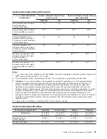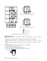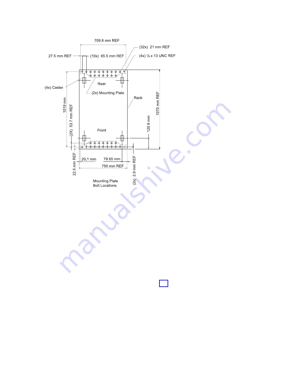
4. Mark the floor around the edge of the mounting plates, as shown in the following illustration:
5.
Remove the mounting bolts from the threaded holes.
6.
Move the rack away from the mounting plates.
7.
Mark the floor at the center of each hole in the mounting plate (including tapped holes).
8.
Remove the mounting plates from the marked locations.
9.
At the marked location of the tapped mounting holes, drill two holes approximately 1 inch to allow
clearance for the ends of the two rack-mounting bolts. The ends of the rack-mounting bolts may
protrude past the thickness of the mounting plate. Drill one hole in each group of anchor bolt location
marks as indicated on the marked floor.
10. Using at least three bolts for each mounting plate, mount the mounting plates to the concrete floor.
Attention:
It is the service representative’s responsibility to complete the following steps.
1. Reposition the system rack over the mounting plates.
2. Place the four rack-mounting bolts through the plate assemblies with the D-washer positioned so that
the straight side of the washer is facing inward toward the system rack.
between the isolator bushing and the floor plate.
4. Turn the rack-mounting bolts three or four rotations into the tapped holes.
5. Turn the leveling foot of the plate assembly down until it contacts the mounting plate, and then level
the rack using the four leveling feet.
6. Lock the leveling feet by tightening the lock nut.
7. Tighten the four rack-mounting bolts into the mounting plates.
Attaching the Rack to a Short or Long Raised Floor:
Chapter 2. Physical Characteristics of Systems
111
Summary of Contents for 7012 397
Page 1: ...RS 6000 and Eserver pSeries Site and Hardware Planning Information SA38 0508 20...
Page 2: ......
Page 3: ...RS 6000 and Eserver pSeries Site and Hardware Planning Information SA38 0508 20...
Page 11: ...Appendix Notices 385 Index 387 Contents ix...
Page 12: ...x Site and Hardware Planning Information...
Page 16: ...xiv Site and Hardware Planning Information...
Page 18: ...xvi Site and Hardware Planning Information...
Page 26: ...8 Site and Hardware Planning Information...
Page 238: ...220 Site and Hardware Planning Information...
Page 246: ...228 Site and Hardware Planning Information...
Page 284: ...266 Site and Hardware Planning Information...
Page 296: ...278 Site and Hardware Planning Information...
Page 366: ...348 Site and Hardware Planning Information...
Page 372: ...Async Adapter Cable Planning Chart 354 Site and Hardware Planning Information...
Page 377: ...Standard I O Cable Planning Chart Chapter 12 Cable Planning 359...
Page 380: ...Cable Planning Chart Other Adapters 362 Site and Hardware Planning Information...
Page 384: ...366 Site and Hardware Planning Information...
Page 402: ...384 Site and Hardware Planning Information...
Page 404: ...386 Site and Hardware Planning Information...
Page 413: ......
Page 414: ...Printed in USA SA38 0508 20...
Page 415: ...Spine information RS 6000 and Eserver pSeries Site and Hardware Planning Information...

