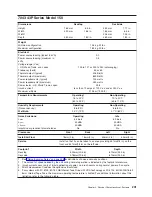
7043 43P Series Model 150
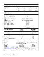
Dimensions
Desktop
Deskside
Height
165 mm
6.5 in.
450 mm
17.7 in.
Width
420 mm
16.5 in.
165 mm
6.5 in.
Width
⁴
235 mm
9.25 in.
Depth
460 mm
18.0 in.
460 mm
18.0 in.
Weight
Minimum configuration
14.5 kg 32 lbs.
Maximum configuration
18.2 kg 40 lbs.
Electrical
Power source loading (typical in kVA)
0.2
Power source loading (maximum in
kVA)
0.4
Voltage range (V ac)
- US, World Trade, and Japan
100 to 127 or 200 to 240 (autoranging)
Frequency (hertz)
50 or 60
Thermal output (typical)
425 Btu/hr
Thermal output (maximum)
850 Btu/hr
Power requirements (typical)
125 watts
Power requirements (maximum)
250 watts
Power factor - US, World Trade, Japan
0.98
Inrush current
³
less than 70 amps at 120 V ac and at 240 V ac
Maximum altitude
2135 m (7000 ft.)
Temperature Requirements
Operating
⁵
16 to 32°C
(60 to 90°F)
Non-Operating
10 to 43°C
(50 to 110°F)
Humidity Requirements
Operating
Non-Operating
(Noncondensing)
8 to 80%
8 to 80%
Wet Bulb
23°C (73°F)
27°C (80°F)
Noise Emissions
¹
Operating
Idle
L
WAd
5.4 bels
5.0 bels
L
pAm
43 dBA
43 dBA
<L
pA
>
m
40 dBA
40 dBA
Impulsive or prominent discrete tones
No
No
Clearances
Front
Back
Left
Right
Install/Air Flow
²
76mm(3 in)
76mm(3 in)
50mm(2 in)
50mm(2 in)
Service
Install so that it can be taken to an area providing 457mm(18 in) on the
front and 457mm(18 in) on the left side.
Footprint
2
Width
Depth
Desktop
520mm(20.5 in)
610mm(24.0 in)
Deskside
318mm(12.5 in)
610mm(24.0 in)
1. See “Noise Emission Notes” on page 336 for definitions of noise emissions positions.
2. The amount of space needed by the unit during normal operation is indicated by the footprint dimensions.
3. Inrush currents occur only at initial application of power, no inrush occurs during normal power off-on cycle.
4. Width measurement includes the optional vertical stand.
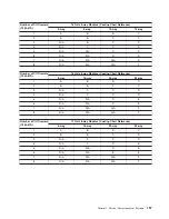
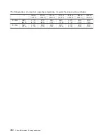
5. For systems with FC 6120: 80/160 GB Internal Tape Drive with VXA Technology or FC 6134: 60/150 GB 16-bit
8mm Internal Tape Drive, the maximum operating temperature is limited. For additional information about this
limitation, refer to the following table.
Chapter 2. Physical Characteristics of Systems
201
Summary of Contents for 7012 397
Page 1: ...RS 6000 and Eserver pSeries Site and Hardware Planning Information SA38 0508 20...
Page 2: ......
Page 3: ...RS 6000 and Eserver pSeries Site and Hardware Planning Information SA38 0508 20...
Page 11: ...Appendix Notices 385 Index 387 Contents ix...
Page 12: ...x Site and Hardware Planning Information...
Page 16: ...xiv Site and Hardware Planning Information...
Page 18: ...xvi Site and Hardware Planning Information...
Page 26: ...8 Site and Hardware Planning Information...
Page 238: ...220 Site and Hardware Planning Information...
Page 246: ...228 Site and Hardware Planning Information...
Page 284: ...266 Site and Hardware Planning Information...
Page 296: ...278 Site and Hardware Planning Information...
Page 366: ...348 Site and Hardware Planning Information...
Page 372: ...Async Adapter Cable Planning Chart 354 Site and Hardware Planning Information...
Page 377: ...Standard I O Cable Planning Chart Chapter 12 Cable Planning 359...
Page 380: ...Cable Planning Chart Other Adapters 362 Site and Hardware Planning Information...
Page 384: ...366 Site and Hardware Planning Information...
Page 402: ...384 Site and Hardware Planning Information...
Page 404: ...386 Site and Hardware Planning Information...
Page 413: ......
Page 414: ...Printed in USA SA38 0508 20...
Page 415: ...Spine information RS 6000 and Eserver pSeries Site and Hardware Planning Information...


