Attach the Rack to a Concrete (Non-Raised) Floor:
Use this procedure to attach the rack to a concrete
(non-raised) floor.
Attention:
It is the customer’s responsibility to ensure the following steps are completed before the
service representative performs the tie-down procedure.
Note:
The customer should obtain the service of a qualified structural engineer to determine appropriate
anchoring of the mounting plates. A minimum of three anchor bolts for each mounting plate must be
used to secure the plates to the concrete floor. Because some of the drilled holes may be aligned
with concrete reinforcement rods below the surface of the concrete floor, additional holes must be
drilled. Each mounting plate must have at least three usable holes, two that are on opposite sides
and opposite ends of each other, and one hole at the center. The mounting plates should be able to
withstand 2500 pounds pulling force on each end.
1.
Be sure the rack is in the correct location.
2.
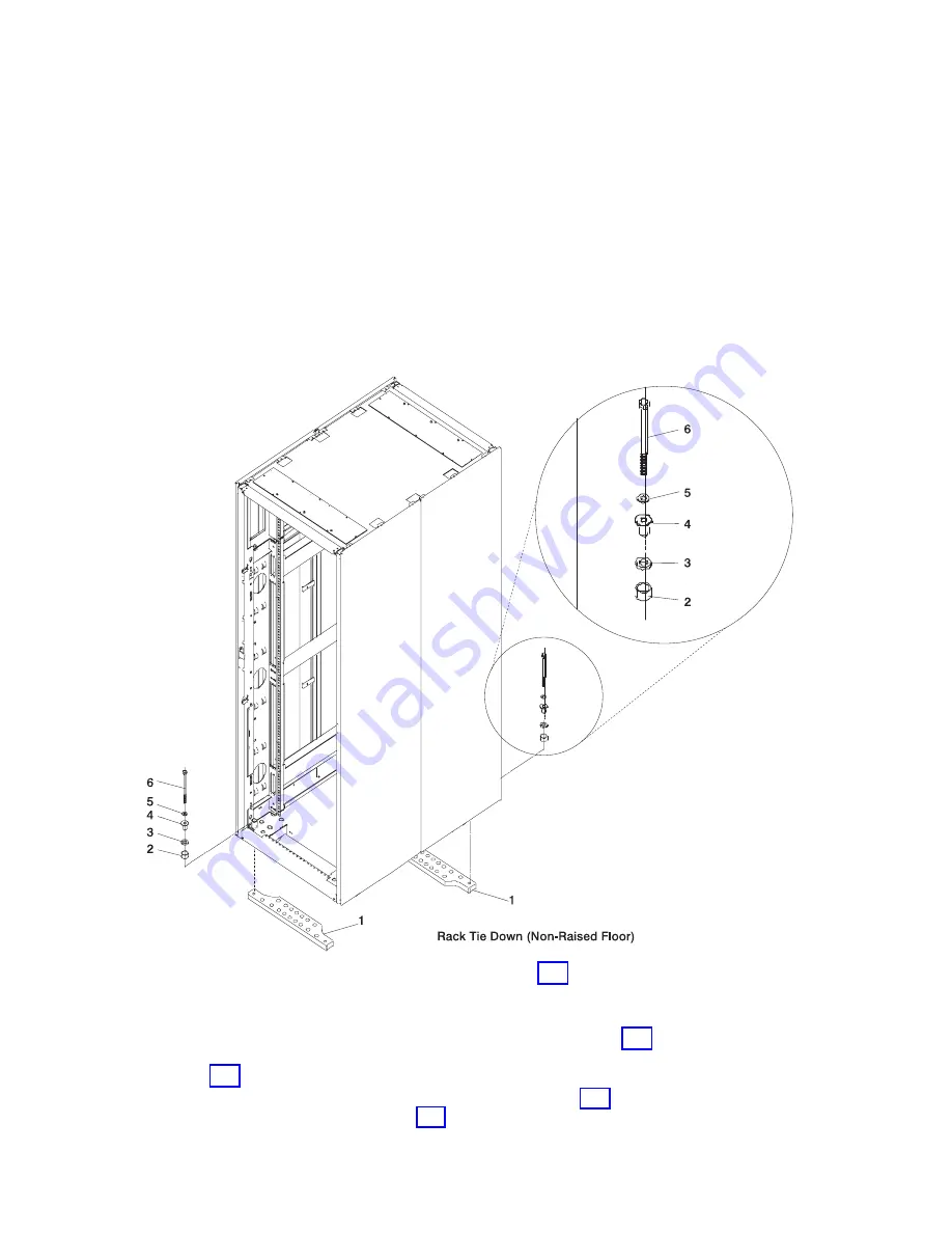
Place the mounting plates (item 1 in illustration on page 187), front and rear, in the approximate
mounting position under the system rack.
3.
To align the mounting plates to the system rack, do the following:
a. Place the four rack-mounting bolts (item 6 in illustration on page 187) through the plate assembly
holes at the bottom of the rack. Install the bushings and washers (item 4 and 5 in illustration on
page 187) to ensure bolt positioning.
b. Position the mounting plates (item 1 in illustration on page 187) under the four rack-mounting
bolts (item 6 in illustration on page 187) so that the mounting bolts are centered directly over the
tapped holes.
Chapter 2. Physical Characteristics of Systems
187
Summary of Contents for 7012 397
Page 1: ...RS 6000 and Eserver pSeries Site and Hardware Planning Information SA38 0508 20...
Page 2: ......
Page 3: ...RS 6000 and Eserver pSeries Site and Hardware Planning Information SA38 0508 20...
Page 11: ...Appendix Notices 385 Index 387 Contents ix...
Page 12: ...x Site and Hardware Planning Information...
Page 16: ...xiv Site and Hardware Planning Information...
Page 18: ...xvi Site and Hardware Planning Information...
Page 26: ...8 Site and Hardware Planning Information...
Page 238: ...220 Site and Hardware Planning Information...
Page 246: ...228 Site and Hardware Planning Information...
Page 284: ...266 Site and Hardware Planning Information...
Page 296: ...278 Site and Hardware Planning Information...
Page 366: ...348 Site and Hardware Planning Information...
Page 372: ...Async Adapter Cable Planning Chart 354 Site and Hardware Planning Information...
Page 377: ...Standard I O Cable Planning Chart Chapter 12 Cable Planning 359...
Page 380: ...Cable Planning Chart Other Adapters 362 Site and Hardware Planning Information...
Page 384: ...366 Site and Hardware Planning Information...
Page 402: ...384 Site and Hardware Planning Information...
Page 404: ...386 Site and Hardware Planning Information...
Page 413: ......
Page 414: ...Printed in USA SA38 0508 20...
Page 415: ...Spine information RS 6000 and Eserver pSeries Site and Hardware Planning Information...


