


N700E INSTRUCTION MANUAL
3-62
1: Normally Closed (NC) – Form B Configuration
Contact specification
Set 0:
RUN
Even when the PID controller is activated, PIDD can override disable the function. When PIDD
becomes activated, VFD Frequency setpoint follows the value in A01.
Code
Set Value
Description
C13
0
Set Intelligent Relay Out 1 Terminal to RUN Mode
C14
0
Set Intelligent Single Pole Single Throw (SPST) Relay Out Terminal to RUN
Mode
C16
0
Set C14 to Normally Open to Form A configuration
If set to 1, Form B configuration (Normally Closed)
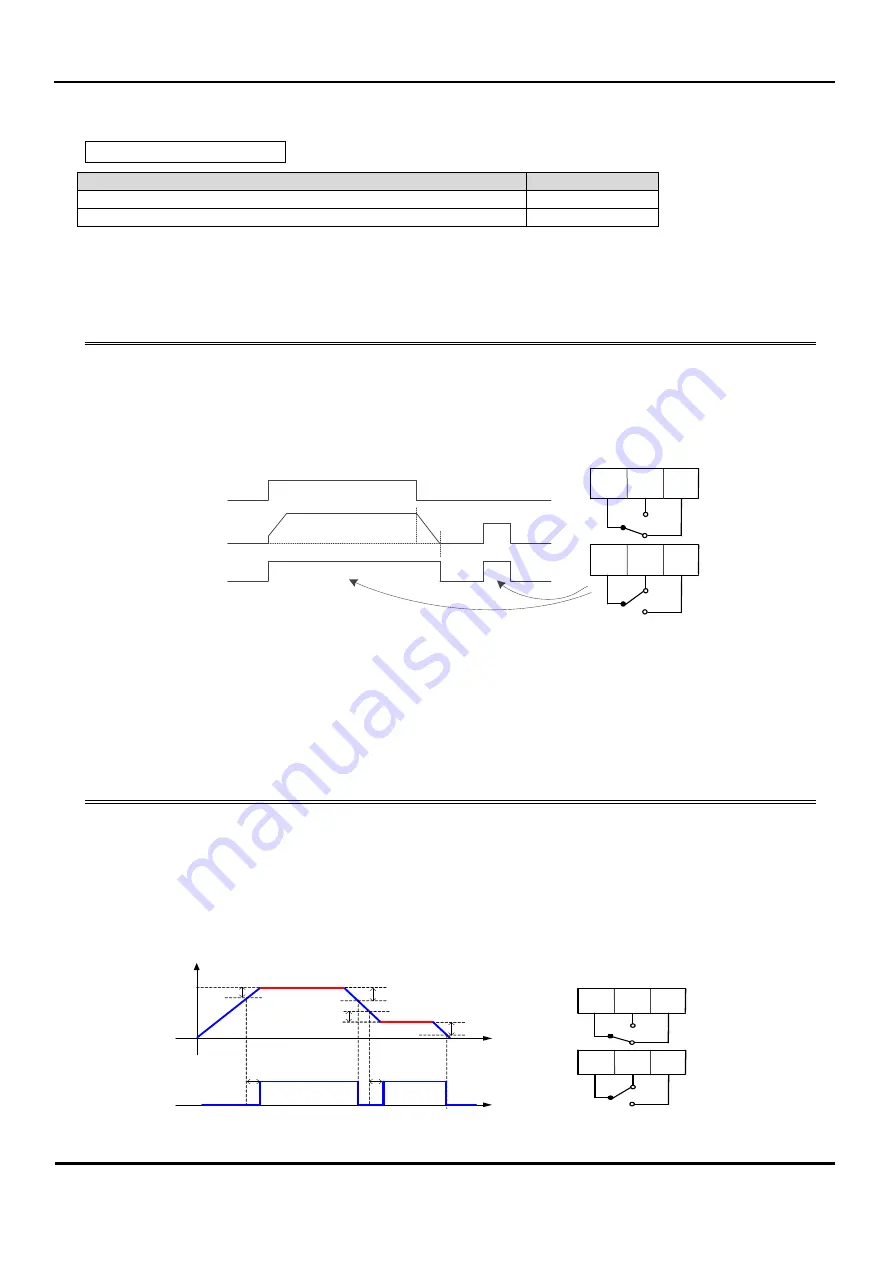
Frequency Out
FW(Run)
RUN Signal
@ RUN signal LOW
DC Braking
AL0 AL1 AL2
AL0 AL1 AL2
@ RUN signal HIGH
Set 1:
Frequency Arrival Signal 1 (FA1)
Set 2: Frequency Arrival Signal 2 (FA2)
Frequency Arrival signals indicate if the VFD output frequency reaches the set frequency specified
in F01. FA1 (FA2) becomes triggered active from 0.5Hz lower set frequency value during
acceleration and 1.5Hz lower during deceleration. But there is 60mS of delay time from the
beginning of its activation.
Code
Set Value
Description
C13
1
Set Intelligent Relay Out 1 Terminal to FA1
C15
0
Set C13 to Normally Open to Form A configuration
If set to 1, Form B configuration (Normally Closed)
F01
0~ Max F
VFD Out Target Frequency
C22
[0 ~ A04] Hz Target Frequency Setpoint during Acceleration for Frequency Arrival Signal
C23
[0 ~ A04] Hz Target Frequency Setpoint during Deceleration for Frequency Arrival Signal
Frequency arrival
signal(FA1)
Output frequency[Hz]
F01 Set Value
0.5Hz
60 msec
1.5Hz
1.5Hz
0.5Hz
60 msec
F01 Set Value
@ FA1 signal LOW
AL0 AL1 AL2
AL0 AL1 AL2
@ FA1 signal HIGH
Maximum
Minimum
AC250V, 2.5A(Resistor load), 0.2A(Inductive load)
AC100V, 10mA
DC30V, 3.0A(Resistor load), 0.7A(Inductive load)
DC5V, 100mA