-269-
ENGINE MANAGEMENT SYSTEM
- 269 -
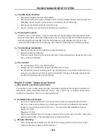
requirements, which are mentioned below -
Control intake air flow
Control idle air flow
Sense throttle position - Provide position feedback to Engine Controller
Provide reactionary force to the throttle
2
.
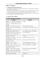
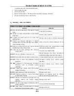
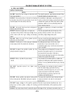
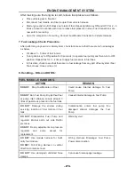
Handling – DOs and DONTs
THROTTLE BODY ASSEMBLY HANDLING
ACTION REASON
DO:
Use care during assembly of harness to throttle
body.
Avoid terminal damage.
DO:
Avoid any liquid contamination in the throttle
body area.
Ensure proper operation.
DO:
Unload and install units one at a time from
packing trays.
Damage may be done to critical components.
DO:
Return any dropped, damaged, or suspect
material with a tag that describes the problem.
(Only warranty cases)
Ensure fast and correct diagnosis of root
DO:
Remove and discard protective caps just before
assembling mating components.
Protects system from contamination, which
can prevent proper operation.
DO:
clean the by pass passage after removing
bottom cover
To ensure good idle stability
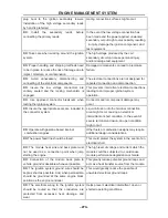
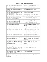
DO NOT:
Use any dropped or impacted unit.
Internal damage may have occurred or
emissions settings may have been upset.
DO NOT:
Store units without protective caps in place. Contamination may impair correct operation.
DO NOT:
Ship or store near saltwater without
protection.
Corrosion buildup may impact proper
operation.
DO NOT:
Exposed to environmental conditions
(Moisture) prior to complete vehicle
installation.
Corrosion buildup may impact proper
operation.
DO NOT:
Apply any voltage other than system
voltage for testing.
Damage could occur.
DO NOT:
Apply excessive band clamp loading
Damage could occur.
DO NOT:
Remove packing in a way that allows
contact between parts.
Minimum air leakage could be affected
and/or other damage could occur.
DO NOT:
Release the throttle cam abruptly from any
position without the throttle linkage
attached.
Damage could occur.
DO NOT:
Let the by pass holes be blocked by dirt or
foreign particles.
This could effect idle stability
DO NOT:
Rake, stage, or handle parts in a manner
that allows contact between parts.
Damage will occur.
Summary of Contents for HS200UTV
Page 3: ......
Page 15: ......
Page 94: ... 79 SPECIFICATIONS 79 HYDROGRAPHIC CHART Hydrographic chart Pressure ...
Page 95: ... 80 SPECIFICATIONS 80 LUBRICATION OIL WAY LUBRICATION OIL WAY Pressure splashing oil ...
Page 248: ... 233 CHASSIS 233 Fuel tank cap Remove the fuel tank cap by turning it counterclockwise ...
Page 263: ... 248 ...
Page 304: ... 289 ...
Page 305: ... 290 ...
Page 306: ... 291 ...
Page 307: ... 292 ...
Page 308: ... 293 ...
Page 309: ... 294 ...
Page 310: ... 295 ...
Page 311: ... 296 ...

