


-182-
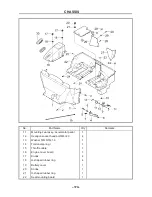
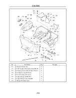
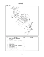
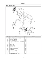
CHASSIS
- 182-
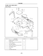
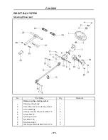
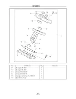
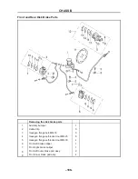
THE STRUCTURE OF STEERING WHEEL
PART
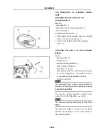
DIASSEMBLING THE PARTS OF THE
STEERING WHEEL
Remove:
• screw M6×16
①
• Decoration cover for steering wheel
②
• Horn assembly
③
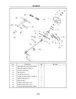
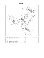
a. Takes down the screw
①
b. Takes down the decoration cover for steering
wheel
②
and horn assembly
③
c. Use the special tools pull out the steering
wheel
④
.
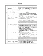
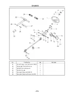
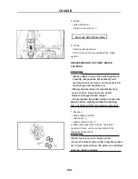
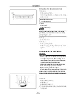
CHECKING THE PARTS OF THE STEERING
WHEEL
Check:
• steering wheel
①
• rocky ledge
②
• reverse turning clearance
③
crack/ break
Replace.
loose/play
Adjust.
the steering wheel to rotate whether nimble,
do not have stagnation.
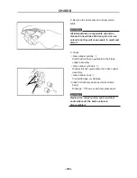
Adjust the torque
of the steering wheel whether obviously
increase
Adjust.
NOTE
:
The steering force cutting which exerts to
transfers in steering wheel outflow boundary
is smaller than 245N.
The reverse running clearance whether does
surpass the limited stipulation
Adjust
NOTE
:
The reverse running clearance is less than
30mm.
The grip part which is covered by the foam
whether has damaged, if it is, must replace a
new steering wheel.
CHASSIS
- 183-
Inspect fastens nut of the steering wheel whether
does have flaw and fissure , if it is, must replace.
Check the internal spline between the steering
wheel and steering column whether have
damaged, if the attrition is serious, must replace
the steering wheel.
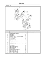
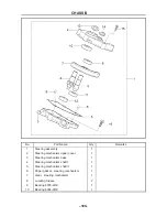
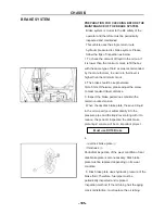
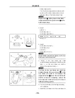
CHECKING AND SERVICE THE STEERING
COLUMN PARTS
1. Check:
• steering column tube
①
• bearing
②
• central axis of
the steering shaft
③
• spline
④
• loosening
⑤
The central axis of t
he steering shaft whether
flexible and moves. If does, dismantle and check
the axis, bearing and retaining ring whether ware
or damaged, according to the inspection situation
to instead the parts.
2. Check:
The two ends of the spline on the central axis
whether is wear out, if so, instead the central
axis.
3. Check:
The spline in the two ends of the central axis
whether have wear, if dose, instead the central
axis.
4. Check:
The steering shaft tube and welding line of the
branch whether have crack and corrosion, if it
does, instead the steering shaft tube.
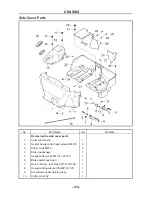
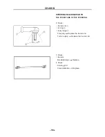
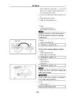
DIASSEMBLING THE STEERING DRIVE AXLE
1. Loose the clamp one piece M8×30 flange bolt
in the cross gimbal, internal spline on the top of
the steering drive axle,
pull out the top of the
steering drive axle.
2. Loose the clamp one piece M8×30 flange bolt in
the cross gimbal, spline on the bottom of the
steering drive axle, pull out the lower of the
steering drive axle.
Summary of Contents for HS200UTV
Page 3: ......
Page 15: ......
Page 94: ... 79 SPECIFICATIONS 79 HYDROGRAPHIC CHART Hydrographic chart Pressure ...
Page 95: ... 80 SPECIFICATIONS 80 LUBRICATION OIL WAY LUBRICATION OIL WAY Pressure splashing oil ...
Page 248: ... 233 CHASSIS 233 Fuel tank cap Remove the fuel tank cap by turning it counterclockwise ...
Page 263: ... 248 ...
Page 304: ... 289 ...
Page 305: ... 290 ...
Page 306: ... 291 ...
Page 307: ... 292 ...
Page 308: ... 293 ...
Page 309: ... 294 ...
Page 310: ... 295 ...
Page 311: ... 296 ...


