-106-
MAINTENCE AND ADJUSTMENT OF THE UTV
- 106 -
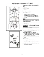
CHECKING THE STEERING SYSTEM
1. place the vehicle on the flat ground .
●
Check:
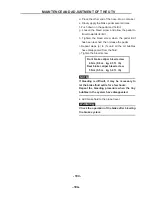
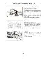
Clamp seat of steeing vertical column and sliding
bearing on the lower end of steering vertical
column,
upper
&
lower and front
&
rear moving steering
bar .If the cleearance is too large, replace the
sliding bearing.
Refer to secrtion “Steering ststem” of chapter 5.
●
Check:
tie-rod ends
Ball pin unit of steering tension rod.
Rotate the steering bar leftward and / or rightward,
Then roate from left to right lightly . If the ball pin
unit of steering tension rod have any vertical
clearance , replace it .
Refer to secrtion “Steering ststem” of chapter 5.
●
Check:
Ball joints and/or wheel bearings Move the
wheels laterally back and forth. Excessive free
play
Replace the front arms (upper and lower)
and/or wheel bearings.
.
MAINTENCE AND ADJUSTMENT OF THE UTV
- 107 -
ADJUSTING THE TOE-IN
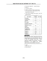
1. Place the vehicle on a level surface.
2. Measure:
• toe-in
Out of specification
Adjust.
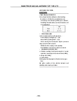
Toe-in
8~ 18 mm (0.00 ~ 0.39 in)
(with tires touching the ground)
NOTE
:
Before measuring the toe-in, make sure that the
tire pressure is correct.
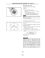
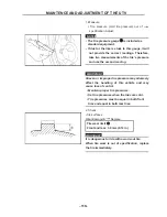
a. Mark both front tire tread centers.
b.Lift the front end of UTV to keep the front wheel
from force .
c. Faster the steering forward . Meagcre the widthe
beetween two marks.
d. Rotate the front tires 180° until the marks are
exactly opposite one another.
e. Measure distance
□
B
between the marks.
f. Calculate the toe-in
using the formula given
below.
Toe-in=
□
B
-
□
A
g. If the toe-in is
incorrect, adjust it
。
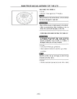
3. Adjust toe-in
WARNING
:
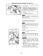
Make sure that left / right tension rods have
turned the same turns . Otherwise the UTV will
still go UTV left and right even though . Operate
the UTV to go forward straightly with steering
bar , easily causing to getting out of contor and
accident . After adjusting the toe-in correctly
drive the UTV to move forward a span of
distance by fastering the steering bar so as to
.
Summary of Contents for HS200UTV
Page 3: ......
Page 15: ......
Page 94: ... 79 SPECIFICATIONS 79 HYDROGRAPHIC CHART Hydrographic chart Pressure ...
Page 95: ... 80 SPECIFICATIONS 80 LUBRICATION OIL WAY LUBRICATION OIL WAY Pressure splashing oil ...
Page 248: ... 233 CHASSIS 233 Fuel tank cap Remove the fuel tank cap by turning it counterclockwise ...
Page 263: ... 248 ...
Page 304: ... 289 ...
Page 305: ... 290 ...
Page 306: ... 291 ...
Page 307: ... 292 ...
Page 308: ... 293 ...
Page 309: ... 294 ...
Page 310: ... 295 ...
Page 311: ... 296 ...


