


-166-
ENGINE
- 166 -
3
、
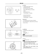
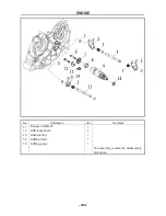
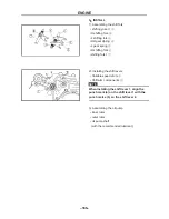
INSTALL
1). Assembling the shift fork
• shifting yoke
Ⅱ①
•H shifting fork
②
•L shifting fork
③
•HR gear dpring
④
•L gear spring
⑤
•R shifting fork
⑥
•shifting fork I
⑦
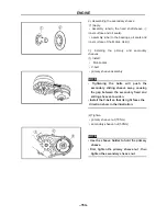
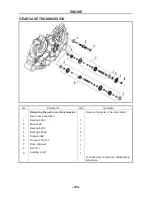
2). Installing the shift levers
• Variable speed drum
①
• Shift arm components
②
NOTE:
When installing the shift lever 1, align the
punch mark (a) on the shift lever 1 with the
punch marks (b) on the shift lever 2.
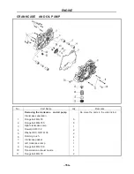
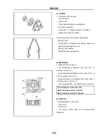
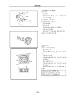
3). Assembling the oil pump
• inner rotor
• outer rotor
• oil pump shaft
(with the recommended lubricant)
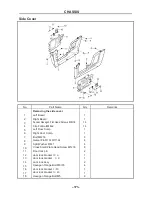
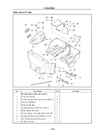
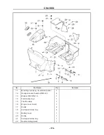
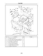
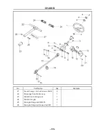
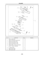
CHASSIS
- 167-
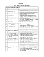
MALFUNCTION INSPECTION
Appearance malfunction inspection
No. Phenomenon
Measure
1 Plastic cover damaged
1. Replace new plastic cover.
2. Check whether installation supporter deformed, repairing
or re-painting is needed before replacing new plastic cover.
3. Re-paste decals and re-rivet warning labels.
2 Bumper damaged
1. Replace new bumper.
2. Check whether installation supporter deformed or
damaged, repairing or re-painting is needed before
replacing new bumper.
3
Frame toe-board damaged
1. Replace new frame toe-board.
2. Check plastic cover whether deformed or damaged,
repairing deformed or damaged plastic cover.
4 Warning labels
Replace damaged and vague warning labels
Brake system malfunction inspection
No. Phenomenon
Measure
1 Locked braking system
1. Check whether brake disc plates deformed.
2. Check whether hydraulic cylinder of brake clamp locked
or brake clamp assembly parts deformed.
2 Brake performance degressive
1. Check whether disc plates abrasion exceeded limits.
2. Check whether brake shoe of clamp abrasion exceeded
limits or polluted by friction material such as oil.
3
、
Check whether the oil cup of brake fluid lack oil.
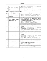
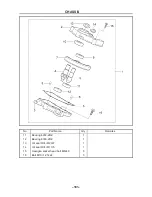
3
Grinding noises emerged from
front brake or brake plate
become red during drive due
to superheat.
1. Check whether brake plate deformed.
2. Check whether hydraulic cylinder of brake clamp locked
or brake clamp assembly parts deformed.
4
Grinding noises emerged from
rear brake or brake plate
become red during drive
1. Check whether brake plate deformed.
2. Check whether hydraulic cylinder of brake clamp locked
or brake clamp assembly parts deformed.
3. Check whether rear brake clamp parking institution
running flexible or return accurately.
5
Off tracking by braking at
high-speed
1. Check whether front brake power deviation from left and
right is within specified scope.
2. Check whether front brake power degressive caused to
rear wheel locked before front wheel in brake process.
3. Check whether left and right absorber spring force
deviation is exceeded specified value.
4. Check whether front wheel and front wheel axle nut
loosen or damaged.
Summary of Contents for HS200UTV
Page 3: ......
Page 15: ......
Page 94: ... 79 SPECIFICATIONS 79 HYDROGRAPHIC CHART Hydrographic chart Pressure ...
Page 95: ... 80 SPECIFICATIONS 80 LUBRICATION OIL WAY LUBRICATION OIL WAY Pressure splashing oil ...
Page 248: ... 233 CHASSIS 233 Fuel tank cap Remove the fuel tank cap by turning it counterclockwise ...
Page 263: ... 248 ...
Page 304: ... 289 ...
Page 305: ... 290 ...
Page 306: ... 291 ...
Page 307: ... 292 ...
Page 308: ... 293 ...
Page 309: ... 294 ...
Page 310: ... 295 ...
Page 311: ... 296 ...


