-267-
ENGINE MANAGEMENT SYSTEM
- 267 -
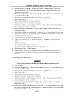
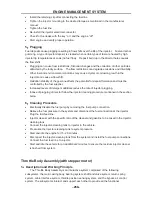
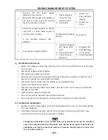
Carefully installing the harness connector will prevent terminal damage. Listen for a
positive audible click from the connector retention device — this ensures that it is fully
engaged. Shut off ignition.
Disconnect negative battery cable to avoid possible fuel discharge if an accidental attempt
is made to start the engine.
Disconnect the electrical connector from the injector wiring harness.
Relieve fuel pressure
Remove the retaining clip from the fuel injector.
Remove the fuel line connection from the injector
Carefully clean debris from the interface surfaces. Do not damage seal mating surfaces.
Remove the injector from the manifold
Apply a light coating of a lubricant to both the upper and lower injector seal ring of the
replacement injector.
Install the new injector into the manifold. Check that the injector is installed in the original
orientation to maintain proper spray targeting, and that the retaining clip is properly seated
on the injector and the fuel line
Install the retaining clip after connecting the fuel line
Tighten the injector mounting to the desired torque as mentioned in the manufacturer
manual
Tighten the fuel line
Re-install the injector electrical connector
Check for fuel leaks with the key “on” and the engine “off”
Start engine and verify proper operation.
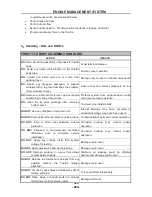
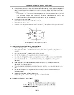
or spray pattern, do not rotate the injector in the fuel rail assembly to install the injector
electrical connector. This may dislodge the retaining clip, and result in improper spray
orientation
4
.
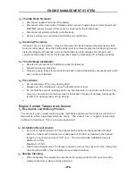
Replacement Techniques
WARNING:
The injector and all associated hardware may be extremely hot.
Shut off ignition.
Disconnect negative battery cable to avoid possible fuel discharge if an accidental attempt
is made to start the engine.
Disconnect the electrical connector from the injector wiring harness.
Relieve fuel pressure
Remove the retaining clip from the fuel injector.
Remove the fuel line connection from the injector
Carefully clean debris from the interface surfaces. Do not damage seal mating surfaces.
Remove the injector from the manifold
Apply a light coating of a lubricant to both the upper and lower injector seal ring of the
replacement injector.
Install the new injector into the manifold. Check that the injector is installed in the original
orientation to maintain proper spray targeting, and that the retaining clip is properly seated
on the injector and the fuel line
Summary of Contents for HS200UTV
Page 3: ......
Page 15: ......
Page 94: ... 79 SPECIFICATIONS 79 HYDROGRAPHIC CHART Hydrographic chart Pressure ...
Page 95: ... 80 SPECIFICATIONS 80 LUBRICATION OIL WAY LUBRICATION OIL WAY Pressure splashing oil ...
Page 248: ... 233 CHASSIS 233 Fuel tank cap Remove the fuel tank cap by turning it counterclockwise ...
Page 263: ... 248 ...
Page 304: ... 289 ...
Page 305: ... 290 ...
Page 306: ... 291 ...
Page 307: ... 292 ...
Page 308: ... 293 ...
Page 309: ... 294 ...
Page 310: ... 295 ...
Page 311: ... 296 ...

