


-160-
ENGINE
- 160 -
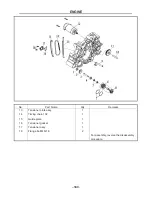
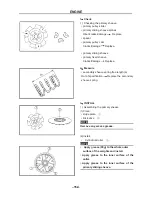
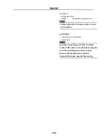
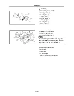
(4)Tighten:
• crankcase bolts
(follow
the pro
per tightening sequence)
NOTE:
• Tighten the bolts in stages, using a crises
cross pattern.
3
、
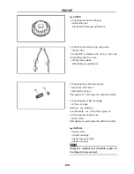
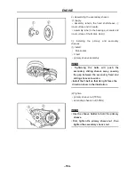
INSTALL
1). Installing the crankshaft
• crankshaft
NOTE:
Hold the connecting rod at the Top Dead
Center (TDC) with one hand while turning the
nut of the installing tool with the other.
Operate the installing tool until the
crankshaft bottoms against the bearing.
ENGINE
- 161 -
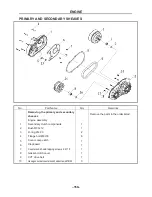
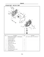
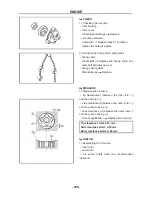
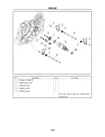
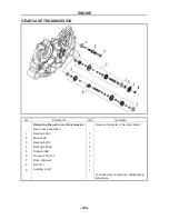
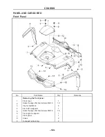
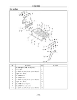
SHIFT AND CONTROL MECHANISM
No.
Part Name
Qty Remarks
Removing the
shifting fork and Variable
speed drum
Remove the parts in the order liste
Gear case separation
1
Cir clip
Φ
12
5
2
Shifting fork
2
3
HR gear dpring
2
4
Shifting yoke
Ⅱ
1
5
L gear spring
1
6
Flange bolt M6×25
1
7
Gate shift
1
8
Needle bearing
1
9
Variable speed drum
1
10 Oil seal 14×22×5
1
Summary of Contents for HS200UTV
Page 3: ......
Page 15: ......
Page 94: ... 79 SPECIFICATIONS 79 HYDROGRAPHIC CHART Hydrographic chart Pressure ...
Page 95: ... 80 SPECIFICATIONS 80 LUBRICATION OIL WAY LUBRICATION OIL WAY Pressure splashing oil ...
Page 248: ... 233 CHASSIS 233 Fuel tank cap Remove the fuel tank cap by turning it counterclockwise ...
Page 263: ... 248 ...
Page 304: ... 289 ...
Page 305: ... 290 ...
Page 306: ... 291 ...
Page 307: ... 292 ...
Page 308: ... 293 ...
Page 309: ... 294 ...
Page 310: ... 295 ...
Page 311: ... 296 ...


