-258-
ELECTRICAL COMPONENTS
- 258 -
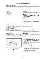
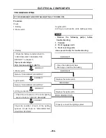
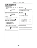
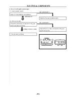
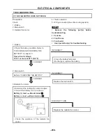
5. If the coolant temperature warning light does not come on when the main switch to “ON”, or
if the coolant temperature warning light does not come on when the temperature is high
(more than 117 ~ 123 °C (242.6 ~ 253.4 °F):
(1)
.
Connection reliability
Check whether the wire connected to the
sensor is strong
CONTINUITY
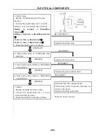
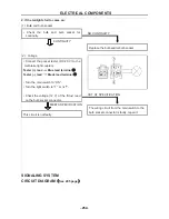
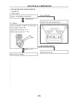
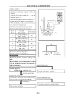
(2). Thermo switch 1
• Remove the thermo switch 1 from the
cylinder head.
• Connect the pocket tester (
Ω
× 1) to the
thermo switch 1
①
.
• Immerse the thermo switch 1 in coolant
②
.
• Check the thermo switch 1 for continuity.
While heating the coolant use a thermometer
③
to record the temperatures.
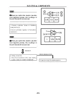
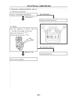
□
A
The thermo switch 1 circuit is open and the
coolant temperature warning light is off.
□
B
The thermo switch 1 circuit is closed and
the coolant temperature warning light is on.
Test
step
Coolant
temperature
Continuity
1
Less than 120 ± 3 °C
(248 ± 5.4 °F)
No
2
More than 120 ± 3 °C
(248 ± 5.4 °F)
Yes
3
More than 113 °C
(235.4 °F)
Yes
4
Less than 113 °C
(235.4 °F)
No
NO CONTINUITY
Repair joint connector
ELECTRICAL COMPONENTS
- 259 -
Test steps 1 & 2: Heating phase
Test steps 3 & 4: Cooling phase
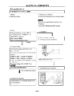
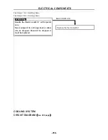
WARNING
:
Handle the thermo switch 1 with special
care.
Never subject it to a strong shock or allow
it to be dropped. Should it be dropped, it
must be replaced.
COOLING SYSTEM
CIRCUIT DIAGRAM
(
See 296 page
)
BAD CONDITION
Replace the thermo switch 1
Summary of Contents for HS200UTV
Page 3: ......
Page 15: ......
Page 94: ... 79 SPECIFICATIONS 79 HYDROGRAPHIC CHART Hydrographic chart Pressure ...
Page 95: ... 80 SPECIFICATIONS 80 LUBRICATION OIL WAY LUBRICATION OIL WAY Pressure splashing oil ...
Page 248: ... 233 CHASSIS 233 Fuel tank cap Remove the fuel tank cap by turning it counterclockwise ...
Page 263: ... 248 ...
Page 304: ... 289 ...
Page 305: ... 290 ...
Page 306: ... 291 ...
Page 307: ... 292 ...
Page 308: ... 293 ...
Page 309: ... 294 ...
Page 310: ... 295 ...
Page 311: ... 296 ...

