


-265-
ENGINE MANAGEMENT SYSTEM
- 265 -
Multec 3.5 Injectors
1
.
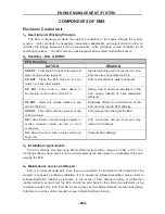
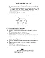
Description and Working Principle
The Multec 3.5 Fuel Injector is an electromechanical device. A magnetic field is generated as
voltage is applied to the solenoid coil.
The resulting magnetic force lifts the core assembly, overcoming manifold vacuum, spring force,
and fuel pressure, allowing fuel to pass through the ball and seat interface to the director.
As the fuel passes through the director, an atomized spray is developed. The injector closes
when the voltage is removed, cutting off the fuel flow.
2
.
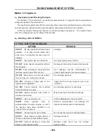
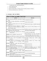
Handling - DOs & DONTs
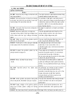
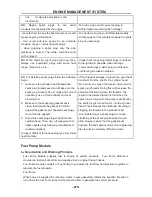
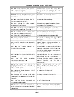
3.5 FUEL INJECTOR HANDLING
ACTION REASON
DO NOT
:
Re-use injector seal rings if at all
possible. If no other choice exists, take
extra care in inspecting the seal rings for
damage.
Leakage.
DO NOT
:
Dip injector tips into lubricants.
Can plug injector spray orifices.
DO NOT
:
Cycle injector repeatedly without
fuel pressure.
Damage to internal mechanical components.
DO NOT
:
Pulse (actuate) a suspected high
leak rate injector (leak >50 sccm air).
Can dislodge internal contamination if
present and preclude root cause analysis.
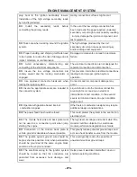
DO NOT
:
Allow water to enter fuel system
from air lines, etc. during leak checks.
Can damage injectors.
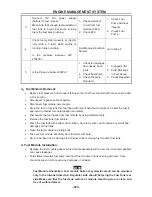
DO NOT
:
Contact or apply load to the
injector tip for installation.
Apply load to 45 deg angle on nylon over
mold see
DO NOT
:
Pound injectors into manifold
during assembly to engine.
Can damage injectors or seal rings.
DO NOT
:
Apply excessive side loads to
electrical connectors.
May cause loss of electrical continuity.
DO NOT
: Use any dropped unit.
Internal damage may have occurred.
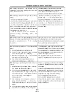
DONOT
:
Store injectors, rails, or
subassemblies including engines on which
the injectors have been installed in an
unprotected environment.
External contamination can damage the
injector electrically and/or mechanically.
DO NOT
:
Use the injector as a handle.
Do not use the injector to lift assemblies
DO NOT
:
Rack, stage, or handle parts in a
manner that allows contact between parts.
Damage will occur.
DO NOT
:
Remove packing in a way that
allows contact between parts.
Damage could occur due ton contact
between parts.
Summary of Contents for HS200UTV
Page 3: ......
Page 15: ......
Page 94: ... 79 SPECIFICATIONS 79 HYDROGRAPHIC CHART Hydrographic chart Pressure ...
Page 95: ... 80 SPECIFICATIONS 80 LUBRICATION OIL WAY LUBRICATION OIL WAY Pressure splashing oil ...
Page 248: ... 233 CHASSIS 233 Fuel tank cap Remove the fuel tank cap by turning it counterclockwise ...
Page 263: ... 248 ...
Page 304: ... 289 ...
Page 305: ... 290 ...
Page 306: ... 291 ...
Page 307: ... 292 ...
Page 308: ... 293 ...
Page 309: ... 294 ...
Page 310: ... 295 ...
Page 311: ... 296 ...


