


-238-
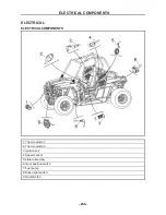
ELECTRICAL COMPONENTS
- 238 -
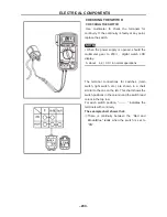
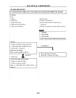
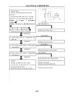
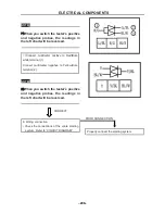
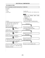
Checking the switch continuity
Refer to “CHECKING THE SWITCH” and check for continuity between lead terminals. Poor connection,
no continuity
Correct or replace.
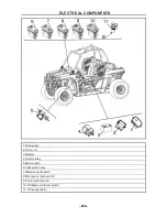
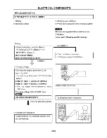
*
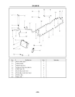
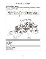
The coupler locations are circled.
1. Parking brake switch
2. Brake light switch
3. Main switch
4. Light switch assy.
5. Distance light switch
6. Emergency lamp switch
7.Turning light switch
8. Windlass controler switch
ELECTRICAL COMPONENTS
- 239 -
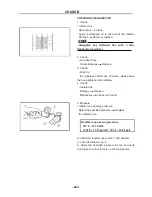
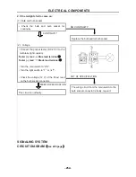
IGNITION SYSTEM
CIRCUIT DIAGRAM
(
See 291 page
)
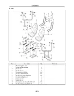
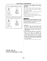
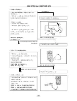
CHECKING THE BULBS AND BULB
SOCKETS
Check each bulb and bulb socket for damage or
wear, proper connections, and also for continuity
between the terminals
Damage/wear
Repair or replace the bulb, bulb
socket or both.
Improperly connected
Properly connect.
Incorrect continuity reading
Repair or replace
the bulb, bulb socket or both.
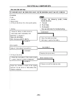
WARNING
:
Since the bulb gets extremely hot, keep
flammable products and your hands away from
the bulb until it has cooled down.
CAUTION:
• Be sure to hold the socket firmly when
removing the bulb. Never pull the lead,
otherwise it may be pulled out of the terminal
in the coupler.
• Avoid touching the glass part of the bulb to
keep it free from oil, otherwise the
transparency of the glass, the life of the bulb
and the luminous flux will be adversely
affected. If the bulb gets soiled, thoroughly
clean it with a cloth moistened with alcohol
or lacquer thinner.
Summary of Contents for HS200UTV
Page 3: ......
Page 15: ......
Page 94: ... 79 SPECIFICATIONS 79 HYDROGRAPHIC CHART Hydrographic chart Pressure ...
Page 95: ... 80 SPECIFICATIONS 80 LUBRICATION OIL WAY LUBRICATION OIL WAY Pressure splashing oil ...
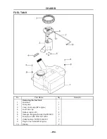
Page 248: ... 233 CHASSIS 233 Fuel tank cap Remove the fuel tank cap by turning it counterclockwise ...
Page 263: ... 248 ...
Page 304: ... 289 ...
Page 305: ... 290 ...
Page 306: ... 291 ...
Page 307: ... 292 ...
Page 308: ... 293 ...
Page 309: ... 294 ...
Page 310: ... 295 ...
Page 311: ... 296 ...


