


9
- 9 -
STARTER MOTOR
………………………………………………………………………… 247
CHARGING SYSTEM
……………………………………………………………………… 247
Circuit diagram………………………………………………………………………… 247
Troubleshooting……………………………………………………………………… 248
LIGHTING SYSTEM
………………………………………………………………………… 249
Circuit diagram………………………………………………………………………… 249
Troubleshooting……………………………………………………………………… 250
Checking the lighting system…………………………………………………… 251
SIGNALING SYSTEM
……………………………………………………………………… 252
Circuit diagram………………………………………………………………………… 252
Troubleshooting……………………………………………………………………… 253
Checking the signal system……………………………………………………… 254
COOLING SYSTEM
………………………………………………………………………… 259
Circuit diagram………………………………………………………………………… 259
Troubleshooting……………………………………………………………………… 260
CHAPTER 7
ENGINE MANAGEMENT SYSTEM
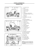
INTRODUCTION
Ems (engine management system) …………………………………………………… 262
Typical components of EMS………………………………………………………………262
Layout of EMS components………………………………………………………………263
COMPONENTS OF EMS
Electronic control unit …………………………………………………………………… 264
Multec 3.5 injectors ……………………………………………………………………… 265
Throttle body assembly(with stepper motor) …………………………………………268
Engine coolant temperature sensor ……………………………………………………270
Intake air pressure and temperature sensor …………………………………………271
Oxygen sensor ………………………………………………………………………… 271
Ignition coil……………………………………………………………………………… 271
Fuel pump module…………………………………………………………………………275
EMS FAULT DIAGNOSIS
Summary of Contents for HS200UTV
Page 3: ......
Page 15: ......
Page 94: ... 79 SPECIFICATIONS 79 HYDROGRAPHIC CHART Hydrographic chart Pressure ...
Page 95: ... 80 SPECIFICATIONS 80 LUBRICATION OIL WAY LUBRICATION OIL WAY Pressure splashing oil ...
Page 248: ... 233 CHASSIS 233 Fuel tank cap Remove the fuel tank cap by turning it counterclockwise ...
Page 263: ... 248 ...
Page 304: ... 289 ...
Page 305: ... 290 ...
Page 306: ... 291 ...
Page 307: ... 292 ...
Page 308: ... 293 ...
Page 309: ... 294 ...
Page 310: ... 295 ...
Page 311: ... 296 ...


