-124-
ENGINE
- 124 -
ENGINE
ENGINE
NOTE
Make
sure the components, oil, adhesive, sealant are from the company or recommended.
2
.
Original removal oil seal
,
gasket, O-ring, piston ring can not be re-assemblied again, make sure all
these parts are new.
1
.
Pay attention to keep dismantled parts orderly, make sure their original positions for reassembling.
4
.
Prevent dismantled parts damaged, clean before measure and assembly, remove the oil with
compressed air. Paint the rotating and sliding parts with specified oil, paint or inject designated
location with recommended grease.
5
.
Bolts and nuts tightening order: pre-fixed bolts, and then tighten them from the large diameter to
small diameter, from inside to outside by diagonal points 2 or 3 times to the specified torque.
Opposite order is for removing bolts and nuts.
6
.
Make sure sealing bolt (with the sealant) must be replaced
7
.
Make sure to use new bearing when remove assembly set up by pressure.
8
.
Determined axial and radial clearance of inner and outer bearing ring by touch, new bear should be
replaced if the clearance is too large or non-rotating flexible.
9
.
Bearing assembly directions: bearing logo should be visible assemblies; confirm bearing outer ring
rotate and move reliably and flexibly when assemble bearing by pressure.
10
.
Oil seal assembly: pay attention to seal side is in the side of oil, logo side outwards, seal side be
painted with grease, and make sure seal side without scratch and oil seal be vertical.
11
.
Before assembly, sealing material attached to all engine covers and crank case combination
surface should be cleaned.
12
.
Before assembly engine, be familiar with engine lubrication circuit, clean and blow oil circuit.
ENGINE
- 125 -
ENGINE
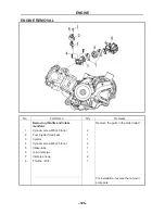
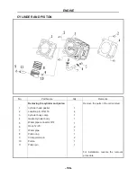
REMOVAL
No
.
Part
Name
Qty
Remarks
Removing
throttle
and
intake
manifold
.
Remove
the
parts
in
the
order
listed
.
1
Cylinder screw M6×20 Inner
2
2
Fuel injector fixed seat
1
3 Injector
1
4
Cylinder screw M6×25 Inner
2
5 Intake-tube
1
6
Joint inlet pipe
1
7
Inlet pipe hoop
2
8 Throttle
(
D34
)
1
For installation, reverse the removal
procedure.
Summary of Contents for HS200UTV
Page 3: ......
Page 15: ......
Page 94: ... 79 SPECIFICATIONS 79 HYDROGRAPHIC CHART Hydrographic chart Pressure ...
Page 95: ... 80 SPECIFICATIONS 80 LUBRICATION OIL WAY LUBRICATION OIL WAY Pressure splashing oil ...
Page 248: ... 233 CHASSIS 233 Fuel tank cap Remove the fuel tank cap by turning it counterclockwise ...
Page 263: ... 248 ...
Page 304: ... 289 ...
Page 305: ... 290 ...
Page 306: ... 291 ...
Page 307: ... 292 ...
Page 308: ... 293 ...
Page 309: ... 294 ...
Page 310: ... 295 ...
Page 311: ... 296 ...

