


-276-
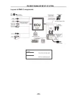
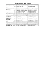
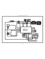
ENGINE MANAGEMENT SYSTEM
- 276 -
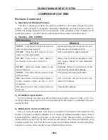
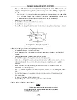
Pressure Regulator
Pressure Regulator is a diaphragm type mechanical device. Fuel flow from filter
enters in the inlet of pressure regulator. Pressure regulator regulates the fuel
pressure at a set pressure by releasing the excessive fuel flow to fuel tank.
2
.
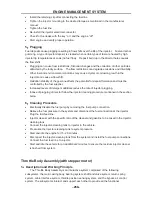
Service Procedure:
Precautions:
Before attempting any service on fuel system, following cautions should be always followed for
personal safety and to avoid system damages.
Disconnect negative cable at battery.
DO NOT smoke, and place ‘No SMOKING” sign near work area
Make sure to have fire extinguisher handy.
Make sure to perform work in well ventilated area and away from any open fire/flames.
Wear Safety glasses
To relieve fuel vapor pressure in fuel tank, remove fuel filler cap fuel filler neck and then
reinstall it.
As fuel lines are at high pressures when the engine is stopped, loosening or disconnecting
fuel line will cause dangerous spout of fuel. Before loosening/ disconnecting fuel lines,
please follow the “Fuel Pressure Relief Procedure” described in this section.
Small amount of fuel may drip after the fuel lines are disconnected. In order to reduce the
risk of personal injury, cover the pipe/ hose ends with suitable blind with no rust or
contamination.
After servicing, make sure that the fuel hoses and clamps are connected according to the
hose fitment instructions given in vehicle instruction manual.
After servicing, please follow the ‘Fuel Leakage Check Procedure’ described in this section.
After servicing make sure to fill at least 3 liters gasoline before pump is primed (ignition key
should be turned on only after ensuring there is minimum 3 liters of fuel in the fuel tank)
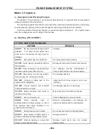
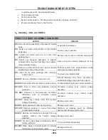
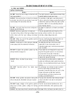
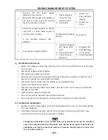
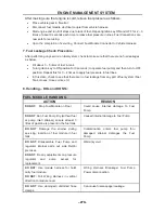
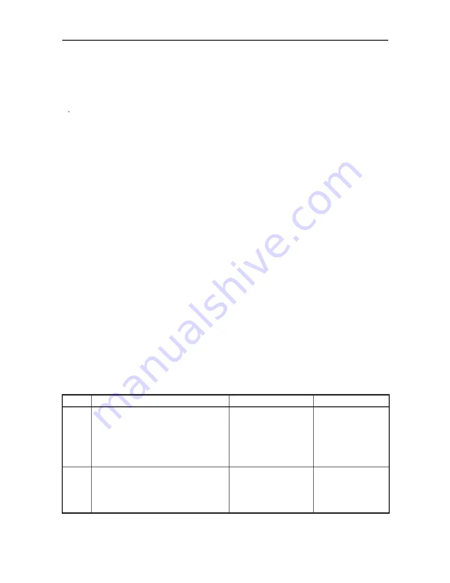
Fuel Module Diagnosis:
Step Action
Yes No
1
Switch on Ignition key. Fuel Pump
primes for 3 seconds when the ignition
key is ON.
Check for fuel pump running noise for 3
seconds after ignition key is ON.
If fuel pump running
noise can be heard, go
to step 4.
If fuel pump running
noise can not be
heard, go to step 2.
2
Disconnect fuel module coupler. Check
voltage at harness coupler.
Is the voltage within 10-14V
Go to step 3
Check the electrical
circuit from Ignition
to fuel module.
ENGINE MANAGEMENT SYSTEM
- 277 -
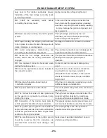
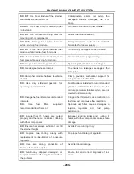
3
Connect 12V DC power supply
(battery) to fuel module.
Make sure that enough fuel available in
fuel tank to avoid fuel pump running
dry.Is the fuel pump running
1. Check electrical
circuit from fuel
module to ECU
2. Check ECU
1. Check Fuel
Pump Harness
integrity
2. Check Fuel
Pump
4
Check fuel system pressure at Injector
inlet (with a T-joint) while engine is
running in idle condition.
Is the pressure between 220 ~
270kPa?
Fuel Module Operation
Normal
Go to Step 5
5
Is the Pressure below 220kPa?
1. Check for leakages
from hoses, hose
joints
2. Check Fuel Pump
3. Check Pressure
Regulator
1. Clogged Filter
2. Kink/ Blockage
in Fuel Hoses
3. Check Regulator
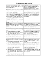
3
.
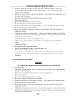
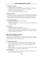
Fuel Module Removal:
Relieve fuel pressure in fuel lines referring to the ‘Fuel Pressure Relief Procedure’ provided
in this section.
Disconnect negative cable at battery.
Disconnect fuel module wire coupler.
Drain the fuel in fuel tank thru fuel filler with help of hand pump (siphon). Collect the fuel in
approved container for contamination and safety.
Disconnect the fuel hoses from fuel module by using standard tools
Remove the fuel tank from vehicle.
Place the fuel tank with bottom up condition. Care to be taken not to cause any scratches/
damages on fuel tank.
Open the fuel module mounting bolts.
Take out fuel module assembly from fuel tank with care
Care to be taken not to damage the strainer while removing fuel module from tank.
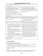
4. Fuel Module Installation:
Replace the fuel module gasket in fuel module assembly with a new one. Old/ used gaskets
can cause leakages.
Fold strainer towards fuel pump and insert fuel module in tank opening with care. Care
should be taken not to cause any damages on strainer.
NOTE
Fuel Module Orientation: Fuel module bolts not symmetrical and can be mounted
only in the intended direction. Regulator side should be facing the Fuel Tank rear
side.Make sure that the fuel tank surface at module mounting area is clean and
free of surface defects.
Summary of Contents for HS200UTV
Page 3: ......
Page 15: ......
Page 94: ... 79 SPECIFICATIONS 79 HYDROGRAPHIC CHART Hydrographic chart Pressure ...
Page 95: ... 80 SPECIFICATIONS 80 LUBRICATION OIL WAY LUBRICATION OIL WAY Pressure splashing oil ...
Page 248: ... 233 CHASSIS 233 Fuel tank cap Remove the fuel tank cap by turning it counterclockwise ...
Page 263: ... 248 ...
Page 304: ... 289 ...
Page 305: ... 290 ...
Page 306: ... 291 ...
Page 307: ... 292 ...
Page 308: ... 293 ...
Page 309: ... 294 ...
Page 310: ... 295 ...
Page 311: ... 296 ...


