


-248-
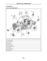
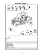
ELECTRICAL COMPONENTS
- 249 -
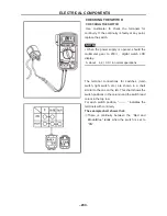
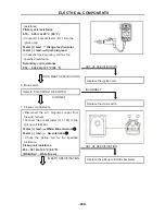
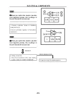
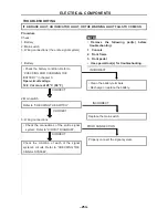
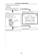
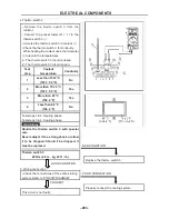
• Connect the pocket tester (Ω × 1) to the
charging coils.
Tester (+) lead
White terminal
①
Tester (–) lead
White terminal
②
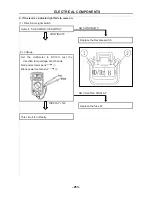
Tester (+) lead
White terminal
①
Tester (–) lead
White terminal
③
• Measure the charging coil resistance.
Charging coil resistance
0.32 ~ 0.43
Ω
at 20 °C (68 °F)
MEETS SPECIFICATION
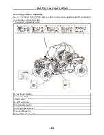
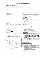
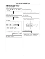
4. Wiring connections
• Check the connections of the entire charging
system. Refer to “CIRCUIT DIAGRAM”.
CORRECT
Replace the rectifier/regulator.
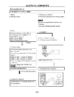
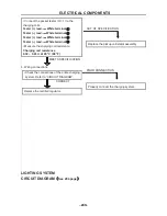
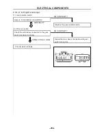
LIGHTING SYSTEM
CIRCUIT DIAGRAM
(
See 294 page
)
OUT OF SPECIFICATION
Replace the pickup coil/stator assembly.
POOR CONNECTION
Properly connect the charging system.
Summary of Contents for HS200UTV
Page 3: ......
Page 15: ......
Page 94: ... 79 SPECIFICATIONS 79 HYDROGRAPHIC CHART Hydrographic chart Pressure ...
Page 95: ... 80 SPECIFICATIONS 80 LUBRICATION OIL WAY LUBRICATION OIL WAY Pressure splashing oil ...
Page 248: ... 233 CHASSIS 233 Fuel tank cap Remove the fuel tank cap by turning it counterclockwise ...
Page 263: ... 248 ...
Page 304: ... 289 ...
Page 305: ... 290 ...
Page 306: ... 291 ...
Page 307: ... 292 ...
Page 308: ... 293 ...
Page 309: ... 294 ...
Page 310: ... 295 ...
Page 311: ... 296 ...


