


-261-
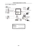
ELECTRICAL COMPONENTS
- 261 -
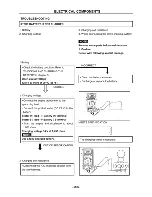
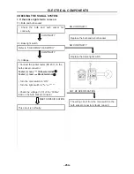
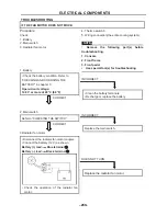
4.Thermo switch 3
• Remove the thermo switch 3 from the
radiator.
• Connect the pocket tester (
Ω
× 1) to the
thermo switch 3
①
.
• Immerse the thermo switch 3 in coolant
②
.
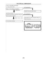
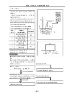
• Check the thermo switch 3 for continuity.
While heating the coolant use a thermometer
③
to record the temperatures.
□
A
The thermo switch 3 circuit is closed.
□
B
The thermo switch 3 circuit is open.
Test
step
Coolant
temperature
Continuity
1
Less than 75±3 °C
(167 ± 5.4 °F)
No
2
More than 75 ± 3 °C
(167 ± 5.4 °F)
Yes
3
More than 68 °C
(154.4 °F)
Yes
4
Less than 68 °C
(154.4 °F)
No
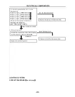
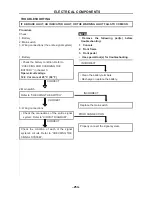
GOOD CONDITION
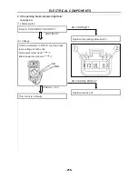
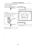
5. Wiring connection
• Check the connections of the entire starting
system. Refer to “CIRCUIT DIAGRAM”
CORRECT
This circuit is not faulty.
Test steps 1 & 2: Heating phase
Test steps 3 & 4: Cooling phase
WARNING
:
Handle the thermo switch 3 with special
care.
Never subject it to a strong shock or allow
it to be dropped. Should it be dropped, it
must be replaced.
Thermo switch 3
28 Nm (2.8 m · kg, 20 ft · lb)
BAD CONDITION
Replace the thermo switch 3
POOR CONNECTION
Properly connect the cooling system.
Summary of Contents for HS200UTV
Page 3: ......
Page 15: ......
Page 94: ... 79 SPECIFICATIONS 79 HYDROGRAPHIC CHART Hydrographic chart Pressure ...
Page 95: ... 80 SPECIFICATIONS 80 LUBRICATION OIL WAY LUBRICATION OIL WAY Pressure splashing oil ...
Page 248: ... 233 CHASSIS 233 Fuel tank cap Remove the fuel tank cap by turning it counterclockwise ...
Page 263: ... 248 ...
Page 304: ... 289 ...
Page 305: ... 290 ...
Page 306: ... 291 ...
Page 307: ... 292 ...
Page 308: ... 293 ...
Page 309: ... 294 ...
Page 310: ... 295 ...
Page 311: ... 296 ...


