


-154-
ENGINE
- 154 -
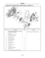
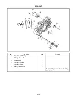
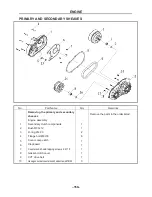
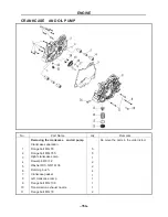
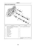
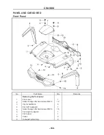
CRANKCASE AND OIL PUMP
No.
Part Name
Qty Remarks
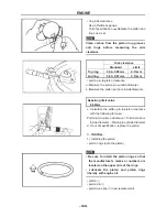
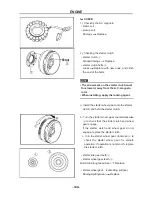
Removing the crankcase and oil pump
Re move the parts in the order listed.
Crankcase separation
1
Flange bolt M6×55
5
2
Flange bolt M6×355
5
3
Right crankcase comp
1
4
Dowel pin
Φ
8×12
2
5
Washer
Φ
10.5×
Φ
19×38
2
6
Damping bush
4
7
Crankcase gasket
1
8
Left crankcase comp
1
9
Flange bolt M6×100
1
10
Transmission exhaust nozzle
1
11
Flange bolt M6×70
2
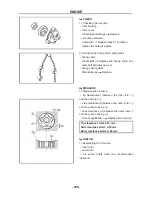
ENGINE
- 155 -
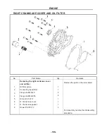
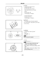
No.
Part Name
Qty
Remarks
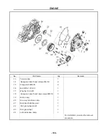
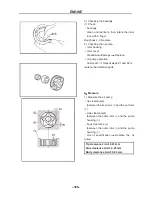
12
Oil drain screw
1
13
O-ring 36×3.5
1
14
Mesh spring
1
15
Oil strainer
1
16
Water pipe connector
Φ
18
1
17
Locating pin 8×12
2
18
O-ring 9×2
2
19
Oil pump comp
1
20
Cross recessed countersunk head screw M6×30
2
21
Bolt M14×1.5×16
1
22
Aluminum gasket 14×22×1
1
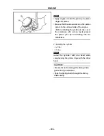
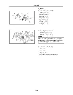
For assembly, reverse the disassembly
procedure.
Summary of Contents for HS200UTV
Page 3: ......
Page 15: ......
Page 94: ... 79 SPECIFICATIONS 79 HYDROGRAPHIC CHART Hydrographic chart Pressure ...
Page 95: ... 80 SPECIFICATIONS 80 LUBRICATION OIL WAY LUBRICATION OIL WAY Pressure splashing oil ...
Page 248: ... 233 CHASSIS 233 Fuel tank cap Remove the fuel tank cap by turning it counterclockwise ...
Page 263: ... 248 ...
Page 304: ... 289 ...
Page 305: ... 290 ...
Page 306: ... 291 ...
Page 307: ... 292 ...
Page 308: ... 293 ...
Page 309: ... 294 ...
Page 310: ... 295 ...
Page 311: ... 296 ...


