-236-
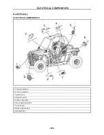
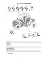
ELECTRICAL COMPONENTS
- 236 -
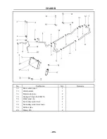
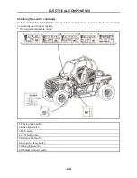
1. Relay assy.
2. ECU unit
3. Battery
4. Starter relay
5. Main switch
6.Light switch assy.
7.Distance light switch
8.Emergency lamp switch
9.Turning light switch
10. Windlass controller switch
11. DC socket assy.
ELECTRICAL COMPONENTS
- 237 -
CHECKING THE SWITCH
CHECKING THE SWITCH
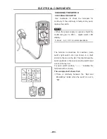
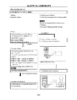
Use multimeter to check the terminals for
continuity. If the continuity is faulty at any point,
replace the switch.
NOTE
:
•
When the power supply is opened, should the
multimeter gear to 200
Ω ,
digital watch LCD
display
。
A about 4.4
±
0.3
Ω
in normal operations
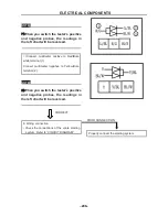
The terminal connections for switches (main
switch, light switch, etc.) are shown in a chart
similar to the one on the left. This chart shows the
switch positions in the column and the switch lead
colors in the top row.
For each switch position, “
” indicates the
terminals with continuity.
The example chart shows that:
①
There is continuity between the “Red and
Brown/Blue” leads when the switch is set to
“ON”.
Summary of Contents for HS200UTV
Page 3: ......
Page 15: ......
Page 94: ... 79 SPECIFICATIONS 79 HYDROGRAPHIC CHART Hydrographic chart Pressure ...
Page 95: ... 80 SPECIFICATIONS 80 LUBRICATION OIL WAY LUBRICATION OIL WAY Pressure splashing oil ...
Page 248: ... 233 CHASSIS 233 Fuel tank cap Remove the fuel tank cap by turning it counterclockwise ...
Page 263: ... 248 ...
Page 304: ... 289 ...
Page 305: ... 290 ...
Page 306: ... 291 ...
Page 307: ... 292 ...
Page 308: ... 293 ...
Page 309: ... 294 ...
Page 310: ... 295 ...
Page 311: ... 296 ...

