


-254-
ELECTRICAL COMPONENTS
- 254 -
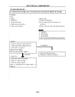
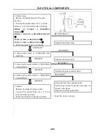
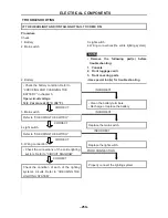
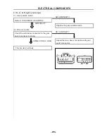
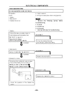
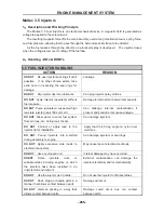
CHECKING THE SIGNAL SYSTEM
1. If the brake lights fail to come on:
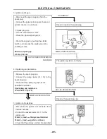
(1). Bulb and bulb socket
• Check the bulb and bulb socket for
continuity.
CONTINUITY
(2). Bake light switch
Refer to “CHECKING THE SWITCH”.
CONTINUITY
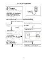
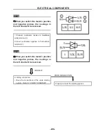
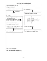
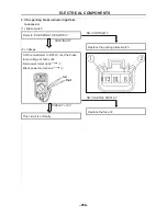
(3). Voltage
• Connect the pocket tester (DC 20 V) to the
bulb socket connector.
Tester (+) lead
Yellow terminal
①
Tester (–) lead
Black terminal
②
• Turn the main switch to “ON”.
• Turn the light switch to “ ” or “
”.
• Check the voltage (12 V) of the “Yellow”
lead on the bulb socket connector.
MEETS SPECIFICATION
This circuit is not faulty.
NO CONTINUITY
Replace the bulb and/or bulb socket.
NO CONTINUITY
Replace the brake light switch.
OUT OF SPECIFICATION
The wiring circuit from the main switch to the
bulb socket connector is faulty, repair it.
ELECTRICAL COMPONENTS
- 255 -
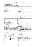
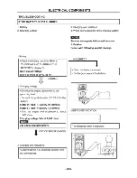
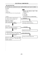
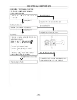
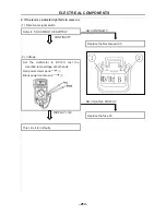
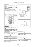
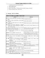
2. If L, H, N, R, light is not bright
(1). Gear position switch
Refer to “CHECKING THE SWITCH”.
CONTINUITY
(2). Wire connection
Check the main beam connected to the gear
switch connector is strong
CONNECTION IS FIRM
This circuit is not faulty.
NO CONTINUITY
Replace the gear position switch
NO CONTINUITY
Repair the main beam connection with gear
switch connector
Summary of Contents for HS200UTV
Page 3: ......
Page 15: ......
Page 94: ... 79 SPECIFICATIONS 79 HYDROGRAPHIC CHART Hydrographic chart Pressure ...
Page 95: ... 80 SPECIFICATIONS 80 LUBRICATION OIL WAY LUBRICATION OIL WAY Pressure splashing oil ...
Page 248: ... 233 CHASSIS 233 Fuel tank cap Remove the fuel tank cap by turning it counterclockwise ...
Page 263: ... 248 ...
Page 304: ... 289 ...
Page 305: ... 290 ...
Page 306: ... 291 ...
Page 307: ... 292 ...
Page 308: ... 293 ...
Page 309: ... 294 ...
Page 310: ... 295 ...
Page 311: ... 296 ...


