16
FMS 1 - Fluorescence Monitoring System
© 2017 Hansatech Instruments Ltd
·
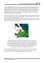
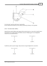
Upper side mount - prevents shading by broad leaf samples, suitable for ambient light
measurement during analysis (Figure 1-7A).
·
Lower front mount - suitable for ambient light measurement during analysis of narrow leaves
which do not shade the sensor (Figure 1-7B). - aligns sensor level with sample for calibration of
fibre-optic light output when upper section slid forward (see below).
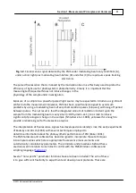
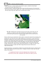
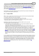
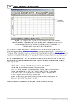
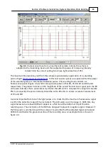
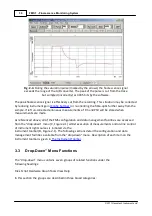
Fig. 1-7B.
The PAR sensor (A) located in the cup on the lower section of the clip. This
position is suitable for actinic light calibration (described below) or simultaneous
PAR monitoring during analysis of narrow samples (B) which do not cover the sensor
in this position.
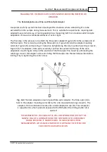
Prior to commencing an experiment it is often useful to measure the output of the saturating lamp
and reference the intensities of actinic light settings that are to be used. In order to do this the
fibre-optic and PAR sensor must be placed in the same geometry and distance that the sample
and fibre would occupy during fluorescence analysis. This can be achieved simply by gently sliding
the upper section of the clip down and forward through its full range of travel so that the PAR
sensor is under the fibre’s field of view. The various light-sources can then be activated and
readings noted from the software display. When light calibration is complete the upper section
should be pushed down and back over the full range of travel to return the fibre to its
measurement position.
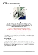
Sample temperature is also monitored simultaneously with PAR and fluorescence. A thermocouple
which stands slightly proud of the lower section is designed to maintain contact with the lower
surface of the sample.
IT IS IMPORTANT TO NOTE THAT THE THERMOCOUPLE IS PROUD OF THE
LOWER LEAF-CLIP SECTION. THEREFORE CARE SHOULD BE TAKEN TO AVOID
Summary of Contents for FMS1
Page 1: ......
Page 7: ...Section 1 Measurement Principles and Hardware ...
Page 21: ...Section 2 Software Installation System Operation Data Handling ...
Page 70: ...70 FMS 1 Fluorescence Monitoring System 2017 Hansatech Instruments Ltd ...
Page 71: ...Section 3 Stand Alone Instrument Operation and Data Upload ...
Page 83: ...83 Section 3 Stand Alone Instrument Operation and Data Upload 2017 Hansatech Instruments Ltd ...

