14
FMS 1 - Fluorescence Monitoring System
© 2017 Hansatech Instruments Ltd
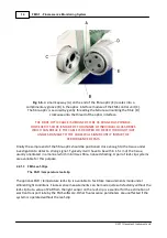
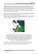
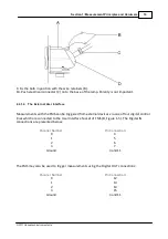
Fig. 1-6.
A small key-way (A) on the end of the fibre-optic (E) locates into a
complimentary groove (B) in the optics interface module of the FMS control unit (C).
The fibre-optic is secured by gently threading the ferrule surrounding the fibre (D)
clockwise onto the thread of the optics interface
.
THE FIBRE OPTIC CABLE IS DESIGNED TO BE AS RUGGED AS POSSIBLE.
HOWEVER ITS CORE IS MADE OF THOUSANDS OF INDIVIDUAL GLASS FIBRES
WHICH CAN BREAK IF THE CABLE IS DROPPED OR FLEXED THROUGH TIGHT
ANGLES. DAMAGE TO THE CABLE WILL SIGNIFICANTLY IMPAIR THE
PERFORMANCE OF FMS.
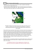
Finally the sample end of the fibre-optic should be positioned close enough to the tissue under
investigation to detect a strong signal. Typically it will have to be within 1.5 cm of the tissue,
usually orientated in a manner which minimises fibre- nduced shading. A pair of leaf-clip systems
are available for this purpose
.
2.2.1.3
FMS Leaf-Clips
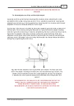
The PAR / temperature leaf-clip
The optional PAR / temperature leaf-clip is available to facilitate measurements made under
ambient light conditions. Fluorescence measurements can be made quite satisfactorily without the
leaf-clip but a value of PAR from the light sensor on the leaf-clip is essential for the estimation of
electron transport rate by the FMS software. Other fluorescence parameters are unaffected if the
system is operated without the leaf-clip.
Summary of Contents for FMS1
Page 1: ......
Page 7: ...Section 1 Measurement Principles and Hardware ...
Page 21: ...Section 2 Software Installation System Operation Data Handling ...
Page 70: ...70 FMS 1 Fluorescence Monitoring System 2017 Hansatech Instruments Ltd ...
Page 71: ...Section 3 Stand Alone Instrument Operation and Data Upload ...
Page 83: ...83 Section 3 Stand Alone Instrument Operation and Data Upload 2017 Hansatech Instruments Ltd ...


