19
Section 1: Measurement Principles and Hardware
© 2017 Hansatech Instruments Ltd
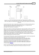
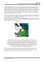
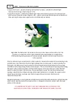
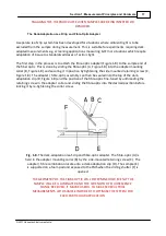
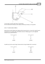
9. Fix the bulb in position with the wire retainers (B).
10. Push electrical connector (C) on to the base of the lamp. Polarity is not important.
2.2.1.4
The External User Interface
Measurements with the FMS can be triggered from external devices via one of four digital control
lines which are connected to the User Interface Socket of FMS (B, Figure 1-5). The Digital IN
connections are presented below:
Channel Number:
Pin Connection:
0
4
1
5
2
6
3
7
Ground
3 and 11
The FMS may also be used to trigger measurements using the Digital OUT connections:
Channel Number:
Pin Connection:
0
12
1
13
2
14
3
15
Ground
3 and 11
Summary of Contents for FMS1
Page 1: ......
Page 7: ...Section 1 Measurement Principles and Hardware ...
Page 21: ...Section 2 Software Installation System Operation Data Handling ...
Page 70: ...70 FMS 1 Fluorescence Monitoring System 2017 Hansatech Instruments Ltd ...
Page 71: ...Section 3 Stand Alone Instrument Operation and Data Upload ...
Page 83: ...83 Section 3 Stand Alone Instrument Operation and Data Upload 2017 Hansatech Instruments Ltd ...

