INSTRUCTIONS
REMOTE-CONTROL MICROPHONE
HM-162B/SW
Thank you for purchasing the HM-162B/SW
REMOTE
-
CONTROL MICROPHONE
. The COMMANDMIC III
TM
is a
remote control microphone for use with the IC-M604
or else.
Please read the connected transceiver’s instruction
manual carefully before installation and operation.
These instructions are just described the remote-
control operations only.
q
BUSY/TRANSMIT INDICATOR
➥
“
B
BU
US
SY
Y
” appears when receiving a signal or when the
squelch opens.
➥
“
T
TX
X
” appears while transmitting.
w
RECEIVER ATTENUATOR INDICATOR
“
L
LO
OC
C
” appears when the Attenuator function is in use.
e
SCRAMBLER INDICATOR
“
S
SC
CR
RA
AM
M
” appears when an optional voice scrambler is acti-
vated.
r
SCAN INDICATOR
➥
Either “
N
NO
OR
RM
MA
AL
L S
SC
CA
AN
N
” or “
P
PR
RI
I-
-S
SC
CA
AN
N 1
16
6
” scan type
appears while scanning.
➥
“
D
DU
UA
AL
L 1
16
6
” appears during dualwatch; “
T
TR
RI
I 1
16
6
” ap-
pears during tri-watch.
t
SELECTOR STATUS INDICATOR
Indicates the [SELECTOR] active status;
“
[
[V
VO
OL
L]
]
” appears when [SELECTOR] as the audio volume.
“
[
[S
SQ
QL
L]
]
” appears when [SELECTOR] as the noise squelch
controller.
“
[
[C
CH
H ]
]
” appears when [SELECTOR] as the channel selector.
y
POSITION INDICATOR
➥
Shows the GPS position data.
• “
?
??
?
” may blink every 2 sec. instead of position data when
the GPS position data is invalid. In this case, the last position
data is held for up to 23.5 hours.
• “
?
??
?
” may blink every 2 sec. instead of position data 4 hours
after the position data is input manually, up until 23.5 hours
have past.
➥
“
N
No
o P
Po
os
si
it
ti
io
on
n
” appears when no GPS receiver is con-
nected and no position data is input manually.
u
TIME ZONE INDICATOR
➥
“
L
Lo
oc
ca
al
l
” appears when the offset time data in the ‘Set
up’ menu is entered.
➥
“
N
No
o T
Ti
im
me
e
” appears when no GPS receiver is connected
and no time data is input manually.
i
CHANNEL COMMENT INDICATOR
Channel comment appears, if programmed.
o
CHANNEL NUMBER READOUT
Indicates the selected operating channel number.
!0
KEY LOCK INDICATOR
➥
Appears while the Key Lock function is in use.
➥
Blinks while the All Key Lock function is in use.
!1
LOW BATTERY INDICATOR
“
” blinks when the battery voltage drops to approx. 10 V
DC or below.
!2
CALL CHANNEL INDICATOR
➥
“
C
CA
AL
LL
L
” appears when the call channel is selected.
➥
“
A
AL
LE
ER
RT
T
” appears when the Weather Alert function is in
use; blinks when an alert tone is received.
!3
CHANNEL GROUP INDICATOR
Indicates whether an International “
I
IN
NT
T
,” U.S.A. “
U
US
SA
A
,”
Canadian “
C
CA
AN
N
” or weather “
W
WX
X
” channel is selected.
!4
DUPLEX INDICATOR
Appears when a duplex channel is selected.
• Duplex channel has a different TX and RX frequency.
!5
TAG CHANNEL INDICATOR
Appears when a tag channel is selected.
!6
POWER INDICATOR
➥
“
2
25
5W
W
” appears when high power is selected.
➥
“
1
1W
W
” appears when low power is selected.
!7
RX SPEAKER INDICATOR
Appears when an RX speaker function is activated.
BUSY
BUSY
-
25W
25W
---
---
INT
INT
---
---
CALL
CALL
LOC
LOC
-
--
--
DUP
DUP
SCRAM
SCRAM
--
TAG
TAG
NORMAL
NORMAL
-
SCAN
SCAN
-
34
34°34.506N
34.506N
123
123°23.236W
23.236W
Local
Local
--
--
1:10
1:10
-
-
CALLING
CALLING
RX
RX
[VOL]
w
q
e
y
u
r
t
!6
!7
!4
!5
!3
!2
o
!0
!1
i
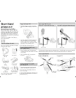
Accessories included with the HM-162B/SW:
Qty.
q
Connection cable (OPC-1540*: 6 m; 20 ft) ....................... 1
w
Mounting base .................................................................. 1
e
Connector cap .................................................................. 1
r
Microphone hanger .......................................................... 1
t
Screws (M3
×
16; tapping) ............................................... 5
*: OPC 1540 has external speaker leads as illustrated at right.
(Yellow: Audio, Black: Speaker ground)
These instructions are described when the HM-162 is connected to the IC-M604. Some operations or indications may be dif-
ferent as these instructions depending on the connecting transceiver.
x
Function display
z
HM-162B/SW supplied accessories
q
w
e
r
t
Yellow
Black
1