26
FMS 1 - Fluorescence Monitoring System
© 2017 Hansatech Instruments Ltd
).
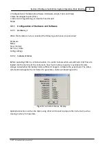
Software configuration, file handing and instrument programming facilities are grouped according
to function on the “drop-down” menu. They are accessed via the mouse or accelerator keys.
Example:
F
iles
S
cript
H
ardware
G
raph
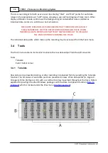
T
ools
V
iew
H
elp
G
raph functions are opened by pressing ALT
G
together.
When a group is selected a sub-menu of related functions is opened. The required function can be
selected with accelerator keys (Key) or by moving the blue-highlight with UP and DOWN cursor
keys to the desired function and pressing RETURN.
Navigation to other the sub-menus is achieved with LEFT and RIGHT cursor keys or mouse. Specific
details of each of the menu function are given in
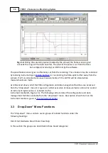
Direct control of FMS light sources and FMS measurement operation is made through the
instrument tool bar (D, Figure 2-1). Light sources are activated by clicking in the appropriate
toggle button with the left hand mouse button. The modulation beam, actinic and far-red light
sources remain illuminated (indicated by an indented button) button until their respective buttons
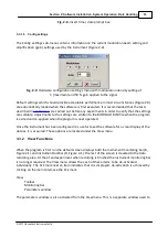
are re-pressed. The extent of actinic illumination is determined by the numeric value (0 to 50) in
the edit box located next to the “Actinic” button (
).
CHANGES IN THE ACTINIC OUTPUT LEVEL ONLY TAKE EFFECT WHEN THE
ACTINIC SOURCE IS INITIALISED. THE ACTINIC LIGHT MUST BE TOGGLED OFF
AND THEN ON TO EFFECT AN INTENSITY CHANGE (
).
The saturation-pulse is activated each time the “Pulse” button is pressed. The button remains
indented during pulse application and automatically re-sets upon termination. Both pulse intensity
(0 - 100) and duration (0.3 - 5.0 sec) are set from accompanying edit boxes on the toolbar (
).
Measurement functions are only available whilst the FMS is recording. A fresh recording is started
by pressing the “Record” button. This automatically triggers the modulation beam which is
essential for fluorescence detection and disables menu functions that should be kept constant
during the recording e.g. instrument configuration settings. Common fluorescence parameters may
be logged via the various parameter buttons located on the instrument toolbar. Detailed
descriptions of each measurement function are given in
. The digital
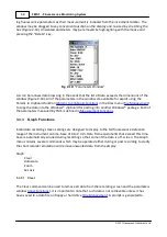
values of each parameter are written to a “Parameter Window” within the software. Under default
settings the “Parameter Window” is not displayed to save screen space. However the software
display may be customised to suit individual requirements via the View function in the “drop-
down” menus (
).
Summary of Contents for FMS1
Page 1: ......
Page 7: ...Section 1 Measurement Principles and Hardware ...
Page 21: ...Section 2 Software Installation System Operation Data Handling ...
Page 70: ...70 FMS 1 Fluorescence Monitoring System 2017 Hansatech Instruments Ltd ...
Page 71: ...Section 3 Stand Alone Instrument Operation and Data Upload ...
Page 83: ...83 Section 3 Stand Alone Instrument Operation and Data Upload 2017 Hansatech Instruments Ltd ...

