15
Section 1: Measurement Principles and Hardware
© 2017 Hansatech Instruments Ltd
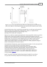
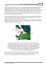
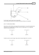
The PAR / temperature leaf-clip consists of a sprung upper section which gently grips the tissue in
a gentle clamping action (C, Figure 1-5A). A grooved neck mounted at 60° to the plane of the
sample (B, Figure 1-5A) accommodates the fibre-optic (A, Figure 1-5A) which is slid into position.
Marked graduations on the neck can be aligned with graduations on the fibre-optic termination to
reference its position for future work, a retaining screw (B, Figure 1-5A) locks it into position
throughout the experiment. The rest of the fibre may be looped over the leaf-clip and hooked to
the rear of the clip to help support its weight.
An electrical connection to the “Leaf-clip” socket on the front panel of the control unit enables use
of the remote trigger switch (F, Figure 1-5A) to activate / abort measurements in “Local” mode
(Chapter 3) and connect on-board thermocouple and
light sensor (C, Figure 1-5A) to the control unit. The leaf-clip may be held in the hand if multiple
samples are being studied or mounted on a standard tripod mount (E, Figure 1-5A) via a thread in
the lower clip section for fixed-position work.
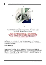
Fig. 1-7A
. A broad leaf sample under investigation in the PAR / temperature
leaf-clip. The fibre-optic (A) is retained in the grooved neck by a screw (B) whilst the
sample (D) is gripped between the upper and lower clip sections. Simultaneous
measurements of ambient light are made with the co-sine corrected PAR sensor (C)
and sample temperature monitored by a thermocouple in contact with the underside
of the sample at (D). The leaf-clip is supported by a tripod mount (E) and
measurements initiated with the remote trigger button (F).
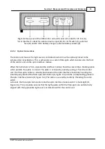
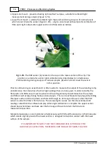
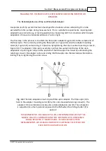
The PAR sensor has been designed for both recording of ambient light intensities during
fluorescence analysis and measurement of FMS actinic and saturating light sources during
instrument set-up. It may be mounted in one of two positions on the leaf-clip:
Summary of Contents for FMS1
Page 1: ......
Page 7: ...Section 1 Measurement Principles and Hardware ...
Page 21: ...Section 2 Software Installation System Operation Data Handling ...
Page 70: ...70 FMS 1 Fluorescence Monitoring System 2017 Hansatech Instruments Ltd ...
Page 71: ...Section 3 Stand Alone Instrument Operation and Data Upload ...
Page 83: ...83 Section 3 Stand Alone Instrument Operation and Data Upload 2017 Hansatech Instruments Ltd ...


