18
FMS 1 - Fluorescence Monitoring System
© 2017 Hansatech Instruments Ltd
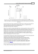
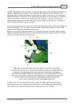
When the fibre-optic has been locked into position the dark-adaptation clip can be removed and
clipped into the experimental sample. The tissue is dark-adapted by sliding the shutter plate
forward (F, Figure 1-8). After a suitable period the tissue
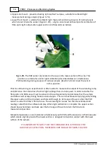
should be dark-adapted and ready for measurement. The adapter / fibre-optic assembly can then
be sealed over the dark-adaptation clip and the shutter blade opened to expose the tissue to the
FMS. The adapter ensures that the sample is completely shielded from ambient light throughout
the measurement.
IN RAPID SCREENING MEASUREMENTS IT MAY BE MORE EFFICIENT TO
DARK-ADAPT A NUMBER OF SAMPLES SIMULTANEOUSLY WITH SEVERAL
CLIPS. REPETITIVE MEASUREMENTS CAN THEN BE MADE BY MOVING THE
FIBRE-OPTIC FROM CLIP TO CLIP.
Hardware Maintenance
The hardware is designed with a minimum of consumable components. The most likely
components to require attention are the halogen lamp, battery and fuses. This section details the
procedures to replace both of these items.
Bulb Replacement
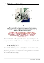
The halogen lamp is an OSRAM 64255 8 V, 20 W unit. The following steps should be followed
during replacement:
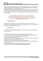
1. Switch off the instrument and allow several minutes for the lamp to cool down.
2. Turn the control unit over and remove the four screws located in the feet of the instrument.
3. Turn the control unit the correct way up and gently remove the lid.
4. Locate the bulb near the front of the unit.
5. Un-clip each side of the wire bulb-retainer individually, tilt the bulb sideways at an angle of 50º
and draw the unit backwards out of the lamp housing.
6. When clear disconnect the electrical connection to the lamp base.
7. Insert the bulb at an angle of 50º and gently slide it into the lamp housing. Avoid touching the
bulb envelope or mirror.
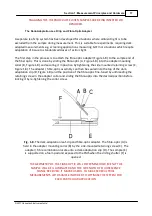
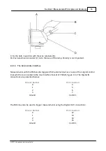
8. Locate the edge of the replacement bulb (D) into the grooves of the lamp
housing (A) and align horizontally.
Do NOT force the bulb into position.
Summary of Contents for FMS1
Page 1: ......
Page 7: ...Section 1 Measurement Principles and Hardware ...
Page 21: ...Section 2 Software Installation System Operation Data Handling ...
Page 70: ...70 FMS 1 Fluorescence Monitoring System 2017 Hansatech Instruments Ltd ...
Page 71: ...Section 3 Stand Alone Instrument Operation and Data Upload ...
Page 83: ...83 Section 3 Stand Alone Instrument Operation and Data Upload 2017 Hansatech Instruments Ltd ...

