28
FMS 1 - Fluorescence Monitoring System
© 2017 Hansatech Instruments Ltd
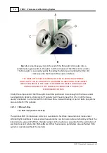
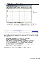
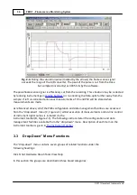
Fig. 2-2
. The sample in this experiment is maintained in the dark under the
modulation beam. The gradual rise in the fluorescence signal is attributable to the
modulation beam driving significant PSII photochemistry. This increase in
fluorescence is known as variable fluorescence.
This phenomena will cause an error in the estimation of several commonly referenced
fluorescence parameters (
). Corrective action requires a reduction in the
frequency of the modulating beam by using a lower modulating beam setting (
) or a
reduction in modulation intensity by increasing the distance between the sample and fibre optic.
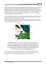
It is also important to check that the instrument is correctly configured to record the maximum
level of fluorescence when the saturation lamp is used. This may achieved with the following
short experiment:
1. Dark-adapt a second piece of spare tissue for a minute of two.
2. Press the “Record” button to start a fresh recording.
3. Set the “Pulse” intensity to medium value in the edit box (e.g. 50 units) and
initiate a pulse by pressing the “Pulse” button. After a further 30 seconds
increase the pulse intensity by 10 units and pulse. Repeat this procedure
incrementing the pulse intensity up to 100 units.
4. After the final pulse stop the recording and autoscale the trace (under the
Graph function in the “drop-down” menu).
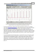
A typical trace from this test on a healthy leaf is shown below (Figure 2-3)
.
Summary of Contents for FMS1
Page 1: ......
Page 7: ...Section 1 Measurement Principles and Hardware ...
Page 21: ...Section 2 Software Installation System Operation Data Handling ...
Page 70: ...70 FMS 1 Fluorescence Monitoring System 2017 Hansatech Instruments Ltd ...
Page 71: ...Section 3 Stand Alone Instrument Operation and Data Upload ...
Page 83: ...83 Section 3 Stand Alone Instrument Operation and Data Upload 2017 Hansatech Instruments Ltd ...

