13
Section 1: Measurement Principles and Hardware
© 2017 Hansatech Instruments Ltd
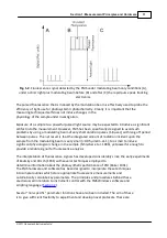
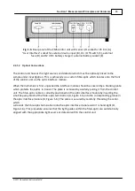
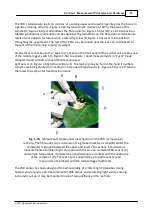
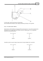
Fig. 1-3.
Rear panel of the FMS control unit with serial I/O socket for PC link (A),
“User Interface” socket for external device input (B), On / Off switch (C), external
fuse (D) and 12 V DC battery charger / external battery socket (E).
2.2.1.2
Optical Connections
The control unit houses the light sources and detector which must be optically linked to the
sample under investigation. This is achieved via a custom fibre-optic which locates onto the front
of the control unit via the optic interface module.
When the instrument is first unpacked the interface module should be covered by a blanking plate
which protects the optics in transit. The plate is removed by carefully pulling it from the control
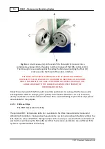
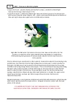
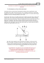
unit. The fibre-optic cable is correctly positioned on the optic interface module by inserting the
small key-way block of the fibre-optic termination (A, Figure 1-6) into the corresponding groove in
the optic interface module (B, Figure 1-6). The cable is secured by carefully threading the collar
which
surrounds the fibre-optic termination onto the optic interface module until it is hand-tight (D,
Figure 1-6). This procedure ensures that the light guides within the fibre-optic are automatically
aligned with the appropriate light source or detector within the control unit.
Summary of Contents for FMS1
Page 1: ......
Page 7: ...Section 1 Measurement Principles and Hardware ...
Page 21: ...Section 2 Software Installation System Operation Data Handling ...
Page 70: ...70 FMS 1 Fluorescence Monitoring System 2017 Hansatech Instruments Ltd ...
Page 71: ...Section 3 Stand Alone Instrument Operation and Data Upload ...
Page 83: ...83 Section 3 Stand Alone Instrument Operation and Data Upload 2017 Hansatech Instruments Ltd ...


