8-43
SECTION 8 –
DUAL PRODUCT SPRAY SYSTEMS
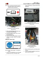
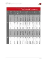
NOTE: The previous tabulations are based on 15-inch/40 cm nozzle spacing. Visit
www.teejet.com for tabulations if choosing spacing other than 15”/40 cm.
Verifying Calibration
To test your system, fill the solution tank
with clean water.
Do not add chemicals
until calibration is complete.
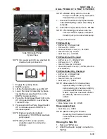
1. Engage the parking brake.
2. Start the engine.
3. Throttle the engine to operating speed.
4. Turn the spray system console ON.
5. Press the Field/Road Button (located on
the Machine Display Home Page) and
change the drive state of the machine to
FIELD.
6. Press the Main Tank Valve Switch
(located on the side console) in the UP
(Open) position.
7. Press the Master Spray Switch (located
on the Hydrostatic Drive Control Handle)
in the ON position.
8. Press all Boom Solution Valve Switches
(located on both Single and Dual Prod-
uct Section Keypads) in the ON position.
Single Product Section Keypad (Sec-
tions 1-9) and Dual Product Section Key-
pad (Sections 10-14).
9.
Primary System
- Press the Manual
(“MAN”) Rate Control Switch (located on
the side console).
10.
Primary System
- Press the Pump
Speed/Rate Switch (located on the side
console) in the “+” position to increase
flow.
11.
Secondary System
- Press and hold the
Rate Control Button (located on the
spray system console). Change to Man-
ual mode (“MAN”).
12.
Secondary System
- Press the Rate
Bump Button (located on the spray sys-
tem console) in the UP position to
increase flow.
13. Ensure there are no leaks and that all
nozzles are spraying a desirable pattern.
14. Continue spraying in the stationary posi-
tion for at least 10 minutes for proper
warm-up of the sprayer and system.
Once the sprayer has had an adequate
warm-up period, you will need to perform a
“self test” to simulate speed (although the
machine will remain stationary).
NOTE: The following “self-test” steps require
measuring flow at given pressure.
•
Collect one nozzle’s spray for one (1)
minute in an adequately sized and
marked container.
•
Verify that the collection equals or is
close to the GPM (l/min) for the nozzle,
pressure, speed, GPA (l/ha), and spac-
ing that you are using.
Also to ensure accuracy, you will need to
verify the flow meter. To do so:
•
Collect one nozzle’s spray for one (1)
minute and multiply it by the number of
nozzles on the boom. This should equal
the amount measured through the flow
meter.
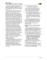
Calculating Spray Width
The spray section widths will need to be
entered into the spray system console during
initial set-up. No matter what the length of the
20
1.0
1.5
2.0
3.0
4.0
5.0
6.0
7.0
4.56
5.58
6.44
7.89
9.11
10.19
11.16
12.05
1710
2093
2415
2959
3416
3821
4185
4519
1140
1395
1610
1973
2278
2548
2790
3013
855
1046
1208
1479
1708
1911
2093
2259
684
837
966
1184
1367
1529
1674
1808
570
698
805
986
1139
1274
1395
1506
489
598
690
845
976
1092
1196
1291
428
523
604
740
854
955
1046
1130
380
465
537
658
759
849
930
1004
342
419
483
592
683
764
837
904
274
335
386
473
547
611
670
723
228
279
322
395
456
510
558
603
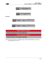
WARNING
Do not add chemicals until calibration is
complete. Contact with chemicals may
cause serious injury or death.


