7-40
SECTION 7 –
SPRAY SYSTEMS
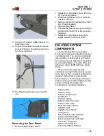
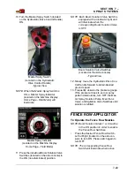
10. Turn the Master Spray Switch (located
on the Hydrostatic Drive Control Handle)
ON.
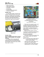
NOTE: When the Master Spray Switch is
ON, a Master Spray Indicator
(located on the Machine Display
Home Page - Field Mode) will
illuminate.
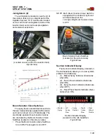
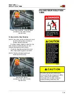
11. Press the individual Boom Solution Valve
Switches (located on the side console) to
the ON (non-illuminated) position.
NOTE: Each Boom Solution Valve Switch is
equipped with an indicator light and
will illuminate when the
corresponding Boom Solution Valve
is OFF.
12. Slowly move the Hydrostatic Drive Con-
trol Handle forward to obtain desired
ground speed.
13. Frequently observe the pressure gauge.
If the pressure drops to zero or spray
pattern deteriorates, turn OFF the Mas-
ter Spray, Solution Pump, Main Tank
Valve, and Agitation Valve Switches until
solution is refilled.
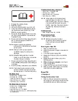
FENCE ROW APPLICATOR
To Operate the Fence Row Nozzles
NOTE: Boom Solution Valves 1 or 9 must be
in the ON position in order to enable
the Fence Row Switches.
•
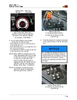
Press the desired Fence Row Switch -
Left or Right (located on the side con-
sole) to turn ON. Press switch again to
turn OFF.
NOTE: The corresponding Fence Row
Switch will illuminate when active.
Master Spray Switch
(Located on the Hydrostatic
Drive Control Handle)
-Typical View
Master Spray Indicator
(Located on the Machine Display
Home Page - Field Mode)
Boom Solution Valve Switches
(Located on the side console)
-Typical View


