


9-31
SECTION 9 –
MAINTENANCE AND STORAGE
7. Measure diagonally (D1 and D2) and
record the measurements.
8. Adjust the wheels until the measure-
ments are equal.
9. Continue to cycle between Steps 5-6 and
7-8 until the width measurements match
and the diagonal measurements match.
Then and only then are the wheels paral-
lel to each other and the frame.
NOTE: To achieve this, both conditions must
be met.
NOTE: The front steering cylinders must
both be centered before
proceeding!
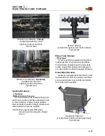
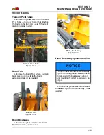
10. Set both cylinders to center by measur-
ing 7.64” (19.4 cm) (as shown in the fol-
lowing photo).
The position sensors should both read
4.4” (11.2 cm) when the cylinders are
centered and in phase.
This is not required for All-Wheel
Steer (AWS) machines, as the cylinder
position sensors can be used to cen-
ter the cylinders.
•
The cylinder sensors must be calibrated
for this position to be accurate.
•
If the cylinders do not center at this mea-
surement, they are not in phase. To re-
phase the cylinders, turn the steering
wheel so that one cylinder is fully
retracted and the other is fully extended.
Turn the steering wheel at least one full
turn past this point. Re-center the cylin-
ders. If the measurements still do not
match, repeat the cylinder air bleed pro-
cedure.
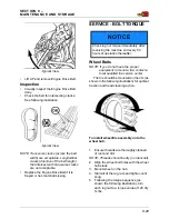
11. With the cylinders centered, adjust the
tie-rods (located on the cylinder rods)
until they line up with the bolt-down hole
(located on the lower air bag plate).
12. Turn the tie-rod one more full turn to
achieve desired amount of toe-in.
•
When the rod ends are turned the final
turn (to establish the desired amount of
toe-in), the rod ends turn in opposite
directions to get each wheel in toe.
•
If the amount of threads showing on the
left and right rod ends differ by more
than four (4) threads, repeat previous
Steps 1-12. If the difference remains,
there may be a tolerance issue in the leg
assembly.
13. Pry wheel in to allow rod end securing
bolt to be inserted.
14. Insert the bolt and secure main bolt and
cylinder jam nut to the proper torque
specification.
Rear Wheels
NOTE: Rear wheels should be set to 0.0”
(0.0 cm) toe in/out.
15. Repeat previous Steps 1-9.
16.
(Non-AWS Machines) -
Set tie rod
assembly to match up with the bolt-down
hole (located on the lower air bag plate).
Insert bolt and secure to the proper
torque specification.
17.
(AWS Machines)
- Repeat Step 10, cen-
tering the rear cylinders at 4.4” (11.2
cm). Insert bolt and secure main bolt and
cylinder jam nut to the proper torque
specification.