


GE Analytical Instruments ©2010
68 of 226
DLM 74001-04 Rev. A
Chapter 4: Basic Analyzer Operation
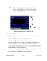
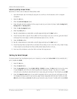
Figure 10: The Sievers 500 RL On-Line TOC Analyzer Main Screen
The
Main
screen is divided into three areas:
1. The Header contains the name of the screen, the date and time, and status icons representing the
following conditions:
• The Key icon (
) displays when basic Password security is enabled.
• The Padlock icon (
) displays when DataGuard is enabled.
• The
W
icon displays when a warning has been issued and the
E
icon displays when an error has
been issued. (See “Reviewing Warnings and Errors” on page 87 for more information.)
2. The Data area shows indicators for the status of the Analyzer’s primary consumables (see “Displaying
Consumables Status” on page 86 for more information). Information about TOC measurements also
displays, depending on which mode the Analyzer is in:
• In the On-Line modes, a trend graph displays on the
Main
screen; to change the scale and specify
which readings display on the graph, see “Graphing Data History” on page 74.
• In Grab mode, a table of data statistics displays on the
Main
screen.
Note:
If Password protection is enabled, you may be required to log in before starting
analysis or proceeding to the Menu screen. If Data guard is enabled, you will be
required to log in before starting analysis or proceeding to the Menu screen. See
“Menu Map — DataGuard (Optional Upgrade)” on page 103 and “Using DataGuard”
on page 105 for more information.
Header
Data area
Status area
Summary of Contents for Sievers 500 RL
Page 8: ...GE Analytical Instruments 2010 8 of 226 DLM 74001 04 Rev A ...
Page 10: ...GE Analytical Instruments 2010 10 of 226 DLM 74001 04 Rev A ...
Page 36: ...GE Analytical Instruments 2010 36 of 220 DLM 74001 04 Rev A ...
Page 66: ...GE Analytical Instruments 2010 66 of 226 DLM 74001 04 Rev A Chapter 3 Installation ...
Page 152: ...GE Analytical Instruments 2010 152 of 226 DLM 74001 04 Rev A Chapter 7 Maintenance ...
Page 170: ...GE Analytical Instruments 2010 170 of 226 DLM 74001 04 Rev A Chapter 8 Troubleshooting ...
Page 178: ...Appendix A GE Analytical Instruments 2010 178 of 186 DLM 74001 04 Rev A ...
Page 185: ...Notes GE Analytical Instruments 2010 185 of 186 DLM 74001 04 Rev A 186 ...
Page 186: ...Notes GE Analytical Instruments 2010 186 of 186 DLM 74001 04 Rev A 186 ...