


GE Analytical Instruments ©2010
48 of 226
DLM 74001-04 Rev. A
Chapter 3: Installation
Step 4: Install Power and Control Wiring
Installation of the power and control wiring requires access to the Analyzer’s electrical enclosure. To remove the
brass-colored cover, use a Phillips screwdriver to loosen the two set screws, then gently pull the cover away from
the Analyzer.
Connecting to a Power Supply
Installation of the Sievers 500 RL On-Line TOC Analyzer requires an external source of AC power connected to
the enclosure using a water-tight conduit connector. The electrical connection should be performed by a
qualified electrician. The Analyzer does not have an internal circuit breaker. An external switch or circuit breaker
is required, and should be installed near the Analyzer and be clearly marked as the disconnecting device for the
Analyzer.
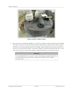
Route the AC power conduit through the lower pass-through port on the left side of the bulkhead, labeled
AC
INLET
. Remove the pass-through cap by loosening the wing nut that secures the cover from inside the Analyzer.
Metallic conduit is required for the Analyzer to meet CE Mark electrical requirements.
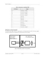
Secure the PVC conduit connector (“strain relief” hub) and washer to the conduit and the Analyzer bulkhead. AC
connections inside the Analyzer are made to the top of the terminal strip (see Figure ), with the line (brown/black
wire) connected to the left port and neutral (blue/white wire) connected to the right port. Connect the grounding
conductor (green and yellow wire) to the ground stud. A terminal ring for 16-14 AWG wire is provided in the
accessories kit; if you use wire of a different gauge, you must provide an appropriate terminal ring.
Wire should be 18-12 AWG, rated to 300 Volts. Strip length should be 8 mm (.33 in). When connecting the wire to
the terminal block, use a small flathead screwdriver (such as the one provided in the accessories kit) to loosen
the screws on the terminal block; insert the wires and then tighten the screws. After connecting the wire, pull on
each connection gently to make sure the connection is secure.
If you are also installing wiring for alarms or 4-20 mA outputs, proceed to the next section. Otherwise, close and
latch the Analyzer door and proceed to “Step 5: Installing the Printer, USB, and Serial Connections” on page 53.
Note:
The Analyzer accessories kit contains two adhesive clips that can be used to store
the double-ended screwdriver and John Guest fitting removal tool inside the
Analyzer. If you choose to use the clips, simply remove the paper backing from each
clip and then firmly press the clip to the desired location inside the Analyzer. Do not
attach the clips to any area that could affect analysis; place the clips inside the door
or on the right bulkhead.
Note:
Before installing any wiring inside the Analyzer, put on a grounding strap for ESD
protection.
Summary of Contents for Sievers 500 RL
Page 8: ...GE Analytical Instruments 2010 8 of 226 DLM 74001 04 Rev A ...
Page 10: ...GE Analytical Instruments 2010 10 of 226 DLM 74001 04 Rev A ...
Page 36: ...GE Analytical Instruments 2010 36 of 220 DLM 74001 04 Rev A ...
Page 66: ...GE Analytical Instruments 2010 66 of 226 DLM 74001 04 Rev A Chapter 3 Installation ...
Page 152: ...GE Analytical Instruments 2010 152 of 226 DLM 74001 04 Rev A Chapter 7 Maintenance ...
Page 170: ...GE Analytical Instruments 2010 170 of 226 DLM 74001 04 Rev A Chapter 8 Troubleshooting ...
Page 178: ...Appendix A GE Analytical Instruments 2010 178 of 186 DLM 74001 04 Rev A ...
Page 185: ...Notes GE Analytical Instruments 2010 185 of 186 DLM 74001 04 Rev A 186 ...
Page 186: ...Notes GE Analytical Instruments 2010 186 of 186 DLM 74001 04 Rev A 186 ...