


GE Analytical Instruments ©2010
148 of 226
DLM 74001-04 Rev. A
Chapter 7: Maintenance
Replacing the In-Line Filter Element
To prevent clogging in on-line configurations, a filter is installed on the sample inlet line. The lifetime of the filter
element depends on the level of particles in the water samples. If monitoring the TOC of the feed water (prior to
purification), the filter element will need to be replaced more often than if monitoring the water after
purification.
If the filter element clogs too frequently, contact GE Analytical Instruments to receive help in the selection of
larger-capacity filters. As the filter is used, the flow rate of water through the
iOS
System will decrease and can
even stop. A simple way to determine if the filter element needs to be changed is to periodically measure the
flow rate of water out the waste line from the
iOS
System and replace the filter element when the flow rate
starts to decrease.
It is desirable to replace the filter element on a routine basis to prevent clogging. For this procedure, two 3/4"
wrenches are needed. To replace the filter element, follow these steps:
1. Stop the Analyzer by pressing the
Stop Analysis
button.
2. Turn off the Analyzer using the main power switch.
3. Shut off the water to the sample inlet system.
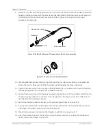
4. Remove the filter by loosening the Swagelok nuts on the 1/4" Teflon tubing and disconnecting the
tubing.
5. Position the 3/4" wrenches on the ends of the filter (see Figure 38). Loosen the adapter on the inlet side
of the filter.
6. Unscrew the spring-loaded inlet adapter, taking care not to lose the spring.
7. Remove the old filter element from the body of the filter.
8. Insert a new filter element into the body of the filter, opened end first.
9. Replace the spring in the inlet adapter and screw the inlet adapter into the body of the filter.
10. Secure the inlet adapter by tightening approximately one-quarter turn past finger-tight.
Table 14: Connections to the DI Water Cartridge
Barb Label
Connection
A
Outlet to pump
B
Inlet from pump
C
Outlet to manifold
D
Inlet from manifold
Summary of Contents for Sievers 500 RL
Page 8: ...GE Analytical Instruments 2010 8 of 226 DLM 74001 04 Rev A ...
Page 10: ...GE Analytical Instruments 2010 10 of 226 DLM 74001 04 Rev A ...
Page 36: ...GE Analytical Instruments 2010 36 of 220 DLM 74001 04 Rev A ...
Page 66: ...GE Analytical Instruments 2010 66 of 226 DLM 74001 04 Rev A Chapter 3 Installation ...
Page 152: ...GE Analytical Instruments 2010 152 of 226 DLM 74001 04 Rev A Chapter 7 Maintenance ...
Page 170: ...GE Analytical Instruments 2010 170 of 226 DLM 74001 04 Rev A Chapter 8 Troubleshooting ...
Page 178: ...Appendix A GE Analytical Instruments 2010 178 of 186 DLM 74001 04 Rev A ...
Page 185: ...Notes GE Analytical Instruments 2010 185 of 186 DLM 74001 04 Rev A 186 ...
Page 186: ...Notes GE Analytical Instruments 2010 186 of 186 DLM 74001 04 Rev A 186 ...