


GE Analytical Instruments ©2010
53 of 226
DLM 74001-04 Rev. A
Chapter 3: Installation
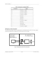
Figure 5: Wiring Option for Binary Input Using External Supply
Step 5: Installing the Printer, USB, and Serial Connections
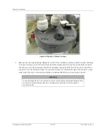
If you have not already done so, replace the electrical enclosure cover by securing the two set screws with a
Phillips screwdriver. Then, close and latch the Analyzer front panel.
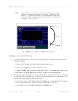
Before installing the printer cable, USB flash drive, or serial cable, you must first remove the cover plate from the
Analyzer. Loosen the two thumb screws on the cover plate and remove the plate.
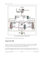
Figure 6: Input and Output Connectors
10 (24 V gnd)
9 (+24 V)
8 (-)
7 (+)
TB2
Internal to Analyzer
Local Control
External to Analyzer
K1
Method 2 - Using Customer’s External Power Supply
Conduit
-
+
K1 = Custom Computer Terminal
12V - 28V
DC
Summary of Contents for Sievers 500 RL
Page 8: ...GE Analytical Instruments 2010 8 of 226 DLM 74001 04 Rev A ...
Page 10: ...GE Analytical Instruments 2010 10 of 226 DLM 74001 04 Rev A ...
Page 36: ...GE Analytical Instruments 2010 36 of 220 DLM 74001 04 Rev A ...
Page 66: ...GE Analytical Instruments 2010 66 of 226 DLM 74001 04 Rev A Chapter 3 Installation ...
Page 152: ...GE Analytical Instruments 2010 152 of 226 DLM 74001 04 Rev A Chapter 7 Maintenance ...
Page 170: ...GE Analytical Instruments 2010 170 of 226 DLM 74001 04 Rev A Chapter 8 Troubleshooting ...
Page 178: ...Appendix A GE Analytical Instruments 2010 178 of 186 DLM 74001 04 Rev A ...
Page 185: ...Notes GE Analytical Instruments 2010 185 of 186 DLM 74001 04 Rev A 186 ...
Page 186: ...Notes GE Analytical Instruments 2010 186 of 186 DLM 74001 04 Rev A 186 ...